15ETL06 Vishay, 15ETL06 Datasheet - Page 4
15ETL06
Manufacturer Part Number
15ETL06
Description
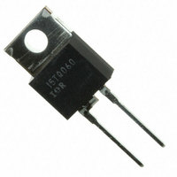
DIODE HYPERFAST 600V 15A TO220AC
Manufacturer
Vishay
Series
FRED Pt™r
Datasheet
1.15ETL06.pdf
(7 pages)
Specifications of 15ETL06
Voltage - Forward (vf) (max) @ If
1.05V @ 15A
Voltage - Dc Reverse (vr) (max)
600V
Current - Average Rectified (io)
15A
Current - Reverse Leakage @ Vr
10µA @ 600V
Diode Type
Standard
Speed
Fast Recovery =< 500ns, > 200mA (Io)
Reverse Recovery Time (trr)
270ns
Mounting Type
Through Hole
Package / Case
TO-220-2 Fused Center, TO-220AC
Lead Free Status / RoHS Status
Contains lead / RoHS non-compliant
Capacitance @ Vr, F
-
Other names
*15ETL06
VS-15ETL06
VS-15ETL06
VS15ETL06
VS15ETL06
VS-15ETL06
VS-15ETL06
VS15ETL06
VS15ETL06
Available stocks
Company
Part Number
Manufacturer
Quantity
Price
Company:

Part Number:
15ETL06
Manufacturer:
IR
Quantity:
12 500
Company:
Part Number:
15ETL06-1
Manufacturer:
IR
Quantity:
12 500
Company:
Part Number:
15ETL06FP
Manufacturer:
IR
Quantity:
12 500
Company:
Part Number:
15ETL06S
Manufacturer:
IR
Quantity:
12 500


15ETL06, 15ETL06FP
Vishay High Power Products
Note
(1)
www.vishay.com
4
Formula used: T
Pd = Forward power loss = I
Pd
REV
= Inverse power loss = V
180
170
160
150
140
130
Fig. 6 - Maximum Allowable Case Temperature vs.
0.01
0
0.1
10
0.00001
1
See note (1)
Square wave (D = 0.50)
Rated V
C
I
F(AV)
= T
(thermal resistance)
J
5
- Average Forward Current (A)
Average Forward Current
- (Pd + Pd
R
Single pulse
applied
F(AV)
0.0001
10
R1
Fig. 5 - Maximum Thermal Impedance Z
REV
x V
x I
DC
FM
) x R
R
(1 - D); I
15
For technical questions, contact: diodes-tech@vishay.com
at (I
thJC
25
20
15
10
F(AV)
5
0
0.001
;
0
Fig. 8 - Forward Power Loss Characteristics
R
20
/D) (see fig. 8);
at V
I
t
F(AV)
Discontinuous Mode PFC, 15 A FRED Pt
1
- Rectangular Pulse Duration (s)
R1
D = 0.50
D = 0.20
D = 0.10
D = 0.05
D = 0.02
D = 0.01
5
- Average Forward Current (A)
= Rated V
25
Ultralow V
DC
0.01
10
R
15
thJC
F
0.1
Hyperfast Rectifier for
Characteristics (FULL-PAK)
D = 0.01
D = 0.02
D = 0.05
D = 0.10
D = 0.20
D = 0.50
RMS limit
20
180
160
140
120
100
80
Fig. 7 - Maximum Allowable Case Temperature vs.
Notes:
1. Duty factor D = t
2. Peak T
0
25
1
Square wave (D = 0.50)
80 % rated V
See note (1)
Average Forward Current (FULL-PAK)
I
F(AV)
J
5
= P
- Average Forward Current (A)
DM
P
DM
R
x Z
10
applied
1
/t
t
10
1
thJC
2
t
2
.
+ T
DC
TM
C
Document Number: 93007
15
.
100
Revision: 24-Nov-08
20
25
Related parts for 15ETL06
Image
Part Number
Description
Manufacturer
Datasheet
Request
R

Part Number:
Description:
15 A, 45V Schottky Rectifier
Manufacturer:
MULTICOMP
Datasheet:
Part Number:
Description:
15 A, 200 V Ultrafast Rectifier, TO-220AC 2 LEAD
Manufacturer:
MULTICOMP
Datasheet:
Part Number:
Description:
15 A, 400 V Ultrafast Rectifier, TO-220AC 2 LEAD
Manufacturer:
MULTICOMP
Datasheet:
Part Number:
Description:
15 A, 600 V Ultrafast Rectifier, TO-220AC 2 LEAD
Manufacturer:
MULTICOMP
Datasheet:
Part Number:
Description:
15 A, 40V Schottky Rectifier
Manufacturer:
MULTICOMP
Datasheet:

Part Number:
Description:
357-036-542-201 CARDEDGE 36POS DL .156 BLK LOPRO
Manufacturer:
Vishay
Datasheet:
Part Number:
Description:
357-036-542-201 CARDEDGE 36POS DL .156 BLK LOPRO
Manufacturer:
Vishay
Datasheet:
Part Number:
Description:
357-036-542-201 CARDEDGE 36POS DL .156 BLK LOPRO
Manufacturer:
Vishay
Datasheet:
Part Number:
Description:
357-036-542-201 CARDEDGE 36POS DL .156 BLK LOPRO
Manufacturer:
Vishay
Datasheet:
Part Number:
Description:
357-036-542-201 CARDEDGE 36POS DL .156 BLK LOPRO
Manufacturer:
Vishay
Datasheet:
Part Number:
Description:
357-036-542-201 CARDEDGE 36POS DL .156 BLK LOPRO
Manufacturer:
Vishay
Datasheet:
Part Number:
Description:
357-036-542-201 CARDEDGE 36POS DL .156 BLK LOPRO
Manufacturer:
Vishay
Datasheet:
Part Number:
Description:
357-036-542-201 CARDEDGE 36POS DL .156 BLK LOPRO
Manufacturer:
Vishay
Datasheet:
Part Number:
Description:
357-036-542-201 CARDEDGE 36POS DL .156 BLK LOPRO
Manufacturer:
Vishay
Datasheet:
Part Number:
Description:
357-036-542-201 CARDEDGE 36POS DL .156 BLK LOPRO
Manufacturer:
Vishay
Datasheet: