A22-GY-10M Omron, A22-GY-10M Datasheet - Page 29
A22-GY-10M
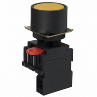
Manufacturer Part Number
A22-GY-10M
Description
PB RND GARD SPST-NO YEL MOM
Manufacturer
Omron
Series
A22r
Type
Standardr
Specifications of A22-GY-10M
Circuit
SPST-NO
Switch Function
Off-Mom
Contact Rating @ Voltage
10A @ 110VAC
Actuator Type
Round Button
Mounting Type
Panel Mount
Termination Style
Screw Terminal
Contact Form
SPST - NO
Contact Rating
10 mAmps
Actuator
Round, Full Guard
Mounting Style
Panel
Illumination
Illuminated
Illumination Color
Yellow
Body Shape
Square
Dielectric Strength
2500 Volts
Insulation Resistance
100 MOhms
Mounting Angle
Straight
Operating Force
29.4 N
Water / Moisture Rating
IP65
Ip Rating
IP65
Lead Free Status / RoHS Status
Lead free / RoHS Compliant
Illumination Type, Color
-
Illumination Voltage (nominal)
-
Lead Free Status / Rohs Status
Lead free / RoHS Compliant
Other names
A22GY10M
Z1459
Z1459


■ Control Box (Enclosure)
Mounting the Switch
The Standard-size Legend Plate Frame can be mounted. Mount the
Frame as shown in the following diagram. Mount the Switch in the
same way as for an ordinary panel.
Creating a Cable Port Hole
Place the tip of a screwdriver on the surface where the cable port
hole is to be created with the cover attached and strike the screw-
driver to punch a hole. Attempts to punch a hole on the other side of
the case will damage the Box.
Securing the Connector Cable
1. Insert the connector into the cable port hole in the Box and secure
2. Open a hole in the thin rubber section of the rubber ring.
3. Pass the tightening cap through the cable, insert the cable into
7 to 9 dia.
9 to 11 dia.
with the fixing nut inside the box.
the connector, and tighten the hexagonal nut to secure the cable.
Lock nut
Cable diameter
Inside
Box
Outside
Rubber washer
Connector
A22Z-3500-1
A22Z-3500-2
Snap-in Legend Plate
Tightening cap
Connector
Cable
■ Installing/Removing the Switch
Installing the Switch Blocks
Hook the small protrusion on the Mounting Latch into the groove on
the other side of the lever, then push up the Switch Block in the direc-
tion indicated by the arrow in the figure below.
Removing the Switch Blocks
Insert a screwdriver between the Mounting Latch and the Switch
Block, then push down the screwdriver in the direction indicated by
the arrow in the following figure.
Blocks
Mounting
Latch
Flat-head
screwdriver
Phillips
screwdriver
Use either of the following screwdrivers.
Pushbutton Switch
3 to 6 mm
3 to 6 mm
Switch Block
Screwdriver
A22
Protrusion
Lever
G-103
Related parts for A22-GY-10M
Image
Part Number
Description
Manufacturer
Datasheet
Request
R

Part Number:
Description:
SWITCH PB ROUND MOM SPST-NC YEL
Manufacturer:
Omron
Datasheet:
Part Number:
Description:
SWITCH PB ROUND MOM DPST-NC YEL
Manufacturer:
Omron
Datasheet:
Part Number:
Description:
SWITCH PB RND MOM SPST-NO/NC YEL
Manufacturer:
Omron
Datasheet:
Part Number:
Description:
SWITCH PB ROUND MOM DPST-NO YEL
Manufacturer:
Omron
Datasheet:
Part Number:
Description:
SWITCH PB ROUND ALT SPST-NC YEL
Manufacturer:
Omron
Datasheet:
Part Number:
Description:
SWITCH PB ROUND ALT SPST-NO YEL
Manufacturer:
Omron
Datasheet:
Part Number:
Description:
SWITCH PB ROUND ALT DPST-NC YEL
Manufacturer:
Omron
Datasheet:
Part Number:
Description:
SWITCH PB RND ALT SPST-NO/NC YEL
Manufacturer:
Omron
Datasheet:
Part Number:
Description:
SWITCH PB ROUND ALT DPST-NO YEL
Manufacturer:
Omron
Datasheet:
Part Number:
Description:
SWITCH PB ILLUM RND MOM SPST YEL
Manufacturer:
Omron
Datasheet:
Part Number:
Description:
SWITCH PB ILLUM RND MOM SPST YEL
Manufacturer:
Omron
Datasheet:
Part Number:
Description:
SWITCH PB ILLUM RND MOM SPST YEL
Manufacturer:
Omron
Datasheet:
Part Number:
Description:
SWITCH PB ILLUM RND MOM SPST YEL
Manufacturer:
Omron
Datasheet:
Part Number:
Description:
SWITCH PB ILLUM RND MOM SPST YEL
Manufacturer:
Omron
Datasheet:
Part Number:
Description:
SWITCH PB ILLUM RND MOM SPST YEL
Manufacturer:
Omron
Datasheet: