A165E-M-03U Omron, A165E-M-03U Datasheet - Page 20
A165E-M-03U
Manufacturer Part Number
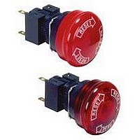
A165E-M-03U
Description
E-stop,non-lighted,40diameter
Manufacturer
Omron
Specifications of A165E-M-03U
Contact Configuration
3PST-NC
Switch Operation
Pushlock Turn Reset
Contact Voltage Ac Nom
250V
Contact Voltage Dc Nom
30V
Contact Current Max
5A
Actuator Style
Round
Control Type
Emergency Stop
Contact Form
3PST - NC
Contact Rating
10 mAmps
Illuminated
N
Lead Free Status / RoHS Status
Lead free / RoHS Compliant
Lead Free Status / RoHS Status
Lead free / RoHS Compliant


Technical Information
•
•
•
•
18
Hand soldering
Automatic
soldering
Do not use soldering flux that contains chlorine. Doing so may
result in metal corrosion.
Perform hand soldering using the appropriate soldering iron.
With the exception of PCB-mounting Switches, when performing
hand soldering, hold the Switch so that the terminals point
downwards so that flux does not get inside the Switch.
Leave a gap of at least 1 mm between the soldered parts and the
surface of the case so that flux does not get inside the Switch.
Correct
Terminal
Method
Incorrect
Dip
soldering
Reflow
soldering
Incorrect
Lead wire
Perform soldering for be-
tween 3 to 5 s with a suit-
able soldering iron.
Large-
capacity
soldering
iron
Soldering iron
Jet soldering
bath
Dip soldering
bath
Infrared reflow
(IR) soldering
bath
Vapor-phase
(VPS) reflow
soldering bath
Soldering
device
Incorrect
Correct
Small-capacity
soldering iron
used for a long
time
Small quantities
Different
materials
Lead wire
terminals
Large quantities
of discrete
terminals
Large quantities
of miniature
SMD terminals
Application
•
•
When applying flux using a brush, use a sponge soaked in flux as
shown below. Do not apply more than is necessary. Also, apply
the flux with the PCB inclined at an angle of less than 80° so that
flux does not flow onto the mounting surface of the Switch.
Do not place PCBs that have had flux applied or have been
soldered on top of each other. Otherwise, the flux on the PCB’s
solder surface may stain the upper part of the Switch or even
permeate the inside of the Switch and cause contact failure.
Incorrect
Flux
Incorrect
Correct
Sponge
soaked in flux
Flux
Lead wire
Terminal
Case
Solder
Brush
Brush
Technical Information
Do not place PCBs
with solder or flux on
top of each other.
80°C
max.
1 mm min.
Related parts for A165E-M-03U
Image
Part Number
Description
Manufacturer
Datasheet
Request
R

Part Number:
Description:
SWITCH, EMERGENCY STOP, DPST-NC, 250VAC
Manufacturer:
Omron
Datasheet:

Part Number:
Description:
ESTOP OPERATOR
Manufacturer:
Omron
Datasheet:
Part Number:
Description:
E-stop,non-lighted,1NC,40diamt
Manufacturer:
Omron
Datasheet:
Part Number:
Description:
ESTOP OPERATOR
Manufacturer:
Omron
Datasheet:
Part Number:
Description:
1 NC CONTACT
Manufacturer:
Omron
Datasheet:

Part Number:
Description:
2 NC CONTACTS
Manufacturer:
Omron
Datasheet:
Part Number:
Description:
2 NC CONTACTS
Manufacturer:
Omron
Datasheet:
Part Number:
Description:
ESTOP OPERATOR
Manufacturer:
Omron
Datasheet:
Part Number:
Description:
E-stop,lighted,1NC,40diameter
Manufacturer:
Omron
Datasheet:
Part Number:
Description:
E-stop,lighted,2NC,40diameter
Manufacturer:
Omron
Datasheet:

Part Number:
Description:
SWITCH PB SQUARE MOM SPDT GREEN
Manufacturer:
Omron
Datasheet:
Part Number:
Description:
SWITCH PB SQUARE MOM SPDT WHITE
Manufacturer:
Omron
Datasheet:
Part Number:
Description:
SWITCH PB SQUARE MOM SPDT YELLOW
Manufacturer:
Omron
Datasheet:
Part Number:
Description:
SWITCH PB RECTANG MOM SPDT BLUE
Manufacturer:
Omron
Datasheet:
Part Number:
Description:
SWITCH PB RECTANG MOM SPDT YEL
Manufacturer:
Omron
Datasheet: