ZEN-10C2AR-A-V2 Omron, ZEN-10C2AR-A-V2 Datasheet
ZEN-10C2AR-A-V2
Specifications of ZEN-10C2AR-A-V2
ZEN10C2ARAV2


Related parts for ZEN-10C2AR-A-V2


ZEN-10C2AR-A-V2 Summary of contents
Page 1
...
Page 2
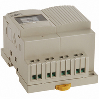
... OMRON products are manufactured for use according to proper procedures by a qualified operator and only for the purposes described in this manual. The ZEN is a compact and highly functional controller that can be used to easily automate small-scale applications. Its development has drawn on OMRON's advanced control technology and expertise in manufacturing various types of controllers ...
Page 3
... Warranty and Limitations of Liability WARRANTY OMRON's exclusive warranty is that the products are free from defects in materials and workmanship for a period of one year (or other period if specified) from date of sale by OMRON. OMRON MAKES NO WARRANTY OR REPRESENTATION, EXPRESS OR IMPLIED, REGARDING NON-INFRINGEMENT, MERCHANTABILITY, OR FITNESS FOR PARTICULAR PURPOSE OF THE PRODUCTS ...
Page 4
... RELIED UPON AS A SAFETY COMPONENT OR PROTECTIVE DEVICE FOR SUCH PURPOSES. Please refer to separate catalogs for OMRON's safety rated products. OMRON shall not be responsible for conformity with any standards, codes, or regulations that apply to the combination of products in the customer’s application or use of the product. ...
Page 5
... PERFORMANCE DATA Performance data given in this manual is provided as a guide for the user in determining suitability and does not constitute a warranty. It may represent the result of OMRON's test conditions, and the users must correlate it to actual application requirements. Actual performance is subject to the OMRON Warranty and Limitations of Liability. ...
Page 6
...
Page 7
... This section provides precautions for using the ZEN Programmable Relays. This information contained in this section is important for the safe and reliable application of the ZEN. You must read this section and understand the information before attempting to set up for a ZEN. Safety Precautions . . . . . . . . . . . . . . . . . . . . . . . . . . . . . . . . . . . . . . . . . . . . . . viii Precautions for Safe Use ...
Page 8
Definition of Precautionary Information The following notation is used in this manual to provide precautions required to ensure safe usage of the product. The safety precautions that are provided are extremely important to safety. Always read and heed the information ...
Page 9
... Never use any battery that has been dropped on the floor or otherwise subjected to excessive shock. Electric shock, fire, or malfunction may occur. Do not disassemble, modify, or repair the ZEN or touch any of the internal parts. Electrical shock may occur. Never touch the I/O terminals, computer connector, Expansion Unit connector, or Battery Unit connector while power is being supplied ...
Page 10
... As a countermeasure for such problems, external safety measures must be provided to ensure safety in the overall system. 4. Outputs from the ZEN may remain ON or OFF due to faults in internal circuits such as output relay fusing or burning, or output transistor destruction countermeasure for such problems, external safety measures must be provided to ensure safety in the overall system. ...
Page 11
... Store the ZEN at an ambient temperature 75°C for LED-type CPU Units and 20 to 75°C for all other types of CPU Units. If the ZEN has been stored at 10°C or lower, allow it to stand at room temperature for 3 hours or longer before turning ON the power supply. ...
Page 12
... The EEPROM has a limited write life. The write life may be exceeded if communications are used frequently to write settings. Consider this in the system design. Other 1. The execution of the ladder program in the ZEN is different from that for other PLCs. Refer to Appendix B Ladder Program Execution in the ZEN Programmable Relay Operation Manual (Cat. No. Z211) when writing the ladder program. 2. ...
Page 13
... Conventions Used in This Manual This user's manual describes the communications functions of CPU Units with com- munications. For information on using other functions, refer to the ZEN Programma- ble Relay Operation Manual. Manual Contents SECTION 1 Communications Methods SECTION 2 CompoWay/F Communications Protocol SECTION 3 Communications Data ...
Page 14
Revision History Manual Revision Code A manual revision code appears as a suffix to the catalog number on the front and back cover of the manual. Man. No. Revision History The following table outlines the changes made to the manual ...
Page 15
Table of Contents SECTION 1 Communications Methods 1.1 Overview of Communications Methods ......................................................... 2 SECTION 2 CompoWay/F Communications Protocol 2.1 Data Format ................................................................................................ 10 2.2 Structure of Command Text ........................................................................ 14 2.3 Detailed Description of the Services ........................................................... 16 2.4 ...
Page 16
xvi ...
Page 17
SECTION 1 Communications Methods This section briefly describes the supported communications methods and how to wire equipment. Refer to this section when setting up equipment. 1.1 Overview of Communications Methods ........................... 2 Introduction................................................................. 2 Communications Specifications.................................. 2 Transmission Procedure............................................. 3 ...
Page 18
... SECTION 1 Communications Methods 1.1 Overview of Communications Methods Introduction A host computer (see note 1) can communicate with the ZEN using the CompoWay/F communications protocol. The host computer is programmed to monitor and set ZEN settings. This manual is thus written from the viewpoint of the host computer nodes including host computers can be connected via CompoWay/F ...
Page 19
... Use a shielded twisted-pair cable with wires of a thickness of AWG28 to AWG14 for communications signal wiring. Note: When using a 1:N connection, set the same communications 1.1 Overview of Communications Methods Response frame sent after the host computer receives a response from the ZEN. Name Model Interface Con- K3SC ...
Page 20
... ZEN so that it can be recognized by the host computer. The node numbers can be set from 00 to 99. Note: The same node number cannot be set for more than one ZEN. If • Communications Baud Rate This parameter sets the baud rate for communications with the host computer ...
Page 21
... This parameter sets the communications parity. Set the parity to none, even, or odd. Setting Communications Parameters Set the communications parameters for the ZEN from the ZEN Support Software or from the RS-485 communications submenu of the CPU Unit. • Settings cannot be changed in RUN mode. Switch to STOP mode first using the following procedure and then set the communications parameters ...
Page 22
... NODE NO COM SPEED DATA BIT STOP BIT 6 The screen at the left will be displayed when the ZEN is in STOP mode. Press the OK Button to display the Menu Screen. Note: This step is not required after switching from RUN Mode to STOP mode. Press the Down Button to move the flashing cursor to RS485 ...
Page 23
Main Menu Press the ESC Button to return to the Menu Screen. SET CLOCK LANGUAGE RS485 OTHER 1.1 Overview of Communications Methods 7 ...
Page 24
SECTION 1 Communications Methods 8 ...
Page 25
SECTION 2 CompoWay/F Communica- tions Protocol This section describes the protocol for communications using the CompoWay/F format. 2.1 Data Format................................................................... 10 2.2 Structure of Command Text ........................................... 14 2.3 Detailed Description of the Services.............................. 16 2.4 Response Code List ...................................................... ...
Page 26
... No responses will be returned from node numbers other than the ones in the above range. • The default setting is 01. Sub-address The sub-address is not used in the ZEN. It must be fixed at “00.” SID • Service ID. The service ID is not used in the ZEN. • Be sure to set it to “00.” ...
Page 27
BCC Calculation Example The BCC (Block Check Character) is determined by calculating the exclusive OR of the bytes from the node number up to ETX. The 8-bit result is written to the BCC byte at the end of the frame. ...
Page 28
SECTION 2 CompoWay/F Communications Protocol End Name code 18 Frame length error The received frame exceeds the specified (supported) num- ber of bytes. • An end code is returned for each command frame received that was addressed to the local ...
Page 29
Example 3 No Node Number Provided Command BCC STX ETX The node number is missing one character. Response No response is made. Example 4 No Sub-address and Illegal BCC Command Node number STX ETX Response Node number Sub-address End code ...
Page 30
SECTION 2 CompoWay/F Communications Protocol 2.2 Structure of Command Text PDU Structure • An MRC (Main Request Code) and SRC (Sub-Request Code) followed by the various required data are transferred in the command text. Service Request PDU • The MRES ...
Page 31
... This service reads the operating status. This service reads ZEN time data. This service sets ZEN time data. This service performs an echoback test. This service switches between RUN and STOP. returned when a memory error has occurred or the Controller is initializing (until normal operation begins after the power is turned ON) ...
Page 32
... Bit Position Bits positions are always 00 except for work bits and HR bits. With the ZEN, bit access supported only for work bits and HR bits. For details on bits and applications methods, refer to 1-4 Memory Areas in the ZEN Programmable Relay Operation Manual (Cat. No. Z211). ...
Page 33
Response 1101 110B 1100 2203 Reading Timers, Counters, and Comparators Reading Timer Types and Time Units Timer types and time units can be read. For timers other than twin timers (normal timer operation), the data is set in the rightmost ...
Page 34
... Comparing Timer/Counter Present Values Using Comparators (P), and 3-12 Comparing the 8-Digit Counter (F) Present Value Using 8-Digit Comparators (G) in the ZEN Programmable Relay Operation Manual (Cat. No. Z211) for details on comparators. Type/number I4 and I5 Variable ...
Page 35
Contents Analog comparator constant Analog comparator operator Comparator operator Comparator PV 8-digit comparator operator 8-digit comparator constant Note: There is only one 8-digit counter (F). Use address 0008 for the PV and address 0009 for the counting speed. • Comparator ...
Page 36
SECTION 2 CompoWay/F Communications Protocol 3. Comparison Operators for 8-Digit Comparator Reading Work Bits and HR Bits Bit positions are specified when reading Work Bits or HR Bits (0 or 1). Example Command [STX]000000101CA000002001 Response [STX]00000010100000000001 20 The comparison data ...
Page 37
... Variable type C0 is read-only. Bit Position Bits positions are always 00 except for work bits and HR bits. With the ZEN, bit access supported only for work bits and HR bits. For details on bits and applications methods, refer to 1-4 Memory Areas in the ZEN Programmable Relay Operation Manual. ...
Page 38
SECTION 2 CompoWay/F Communications Protocol Error Occurred Note: With the Write Variable Area service, Writing Timer and Counter Set Values Reading and Writing Timer Set Values Timer set values (SVs) can be read and written. The rightmost and leftmost four ...
Page 39
... Pulse Operation: The bit is turn ON for the set output time at the set start time and day. Note: refer to 3-8 Using Weekly Timers (@) in the ZEN Programmable • Weekly Timer Data Format The weekly timer data format consists of the following 12 bytes. ...
Page 40
SECTION 2 CompoWay/F Communications Protocol Example [STX]010000102C5000000001005623592359 Pulse Operation End day + Start day + Always 00 The time data is as follows (BCD): Sunday Monday Tuesday Wednesday Thursday Friday Saturday No day designated ...
Page 41
... Calendar timers are built into the ZEN. The calendar timers turn ON between the specified start and end days of the specified months. These can be written using RS-485 communications. Note: refer to 3-9 Using Calendar Timers (*) in the ZEN Programmable • Calendar Timer Data Format The calendar timer data format consists of the following 8 bytes. ...
Page 42
... Buffer size: 36 bytes (= H’0024) Response Code Normal Completion 0000 26 2 Response Model No. code 2 4 Model number ZEN10C4AR-A-V2 ZEN10C4A ZEN10C4DR-D-V2 ZEN10C4D Response Name code Normal completion The bit position is specified when writing. In this example, the bit Bit H2 is turned ON (1). Normal response Buffer size Code Description No errors were found ...
Page 43
Error Occurred Response 1001 2203 Read Controller Status This service reads the operating status and error status. Service Request PDU MRC SRC Service Response PDU MRC SRC Operating Status Operating ...
Page 44
... SECTION 2 CompoWay/F Communications Protocol Error Occurred 1001 Read Time Data This service reads ZEN time data. Service Request PDU MRC SRC 0 2 Service Response PDU MRC SRC 0 2 Note: Each element of the time data (year, month, day of month, hour, 28 Response Name ...
Page 45
... Error Occurred Response 1001 2203 Write Time Data This service reads ZEN time data. Note: Refer to 3-2 Setting the Date and Time in the ZEN Programmable Relay Operation Manual (Cat. No. Z211) for information on setting the date and time. 2.3 Detailed Description of the Services 8 2 ...
Page 46
SECTION 2 CompoWay/F Communications Protocol Service Request PDU MRC SRC 0 2 Note 1: Each element of the time data (year, month, day of month, Note 2: Always 00. MRC SRC 0 2 The time data (BCD follows: ...
Page 47
Response Code Normal Completion Response 0000 Error Occurred Response 1001 1002 1100 2203 Echoback Test This service performs an echoback test. Service Request PDU MRC SRC Service Response PDU MRC SRC ...
Page 48
SECTION 2 CompoWay/F Communications Protocol Response Code Normal Completion 0000 Error Occurred 1001 2203 Operation Command This service switches between RUN and STOP. Service Request PDU MRC SRC Service Response PDU MRC SRC 3 0 ...
Page 49
Detailed Description of the Services Response Error name code 1100 Parameter error 2203 Operation error Cause Command code and related infor- mation are wrong bus error or memory error 2 33 ...
Page 50
SECTION 2 CompoWay/F Communications Protocol 2.4 Response Code List Normal Completion Response Name code 0000 Normal completion Error Occurred Response Name code 0401 Unsupported command 1001 Command too long 1002 Command too short 1101 Area type error 1003 Number of ...
Page 51
SECTION 3 Communications Data This section lists the portions of the variable area that can be set with CompoWay/F communications. 3.1 Variable Area (Data Range) List .................................... 36 35 ...
Page 52
SECTION 3 Communications Data 3.1 Variable Area (Data Range) List The following tables list data ranges by variable type. When there is a section reference for a setting item, refer to that reference for details. Variable TypeC0 (Read-only) Address Data ...
Page 53
Address Data name 0005 Holding timer bit H'00000000 to H'000000FF (-) status 0006 Counter PV H'00000000 to H'0000270F (-) 0007 Counter bit status H'00000000 to H'0000FFFF (-) 0008 8-digit counter PV H'00000000 to H'05F5E0FF (-) 0009 8-digit counter H'00000000 to ...
Page 54
SECTION 3 Communications Data Address Data name 0011 Comparator bit sta- H'00000000 to H'0000FFFF (-) tus 0012 8-digit comparator H'00000008 to H'00000009 (-) operator 0013 CPU Unit output bit H'00000000 to H'0000000F (-) status 0014 CPU Unit input bit H'00000000 ...
Page 55
Variable Type C2 Address Data name 0000 Holding time SV H'00000001 to H'0000270F (S) H'00000001 to H'000026E7 (M:S) H'00000001 to H'000026E7 (H:M) Variable Type C3 Address Data name 0000 Counter SV H'00000001 to H'0000270F (-) Variable Type C4 Address Data ...
Page 56
SECTION 3 Communications Data Variable Type C6 Address Data name 0000 Calendar H'01010101 to H'12311231 (-) timer SV Variable Type C7 Address Data name 0000 Analog com- H'00000000 to H'00000069 (V) parator con- stant Variable Type C8 Address Data name ...
Page 57
Appendix ASCII List ................................................................................. 42 41 ...
Page 58
Appendix ASCII List ...
Page 59
INDEX A addresses ................................................................... 14 analog comparator .................................................... 18 ASCII list .................................................................. 42 B BCC .......................................................................... 10 BCC calculation example ......................................... 11 bit position .......................................................... calendar timer ........................................................... 25 changing from RUN Mode to STOP Mode ...
Page 60
... Export Controls. Buyer shall comply with all applicable laws, regulations and licenses regarding (i) export of products or information; (iii) sale of products to “forbidden” or other proscribed persons; and (ii) disclosure to non-citizens of regulated technology or information. 18. Miscellaneous. (a) Waiver. No failure or delay by Omron in exercising any right and no course of dealing between Buyer and Omron shall operate as a waiver of rights by Omron ...
Page 61
... For US technical support or other inquiries: 800.556.6766 OMRON CANADA, INC. 885 Milner Avenue 1 5 Toronto, Ontario 416.286.6465 OMRON ON-LINE Global - http://www.omron.com USA - http://www.omron.com/oei Canada - http://www.omron.ca Z212-E1-01 10/06 8 ©2006 OMRON ELECTRONICS LLC Printed in the U.S.A. Specifications subject to change without notice. ...