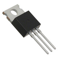
VF20100SG-E3/4W Vishay, VF20100SG-E3/4W Datasheet - Page 2

VF20100SG-E3/4W
Manufacturer Part Number
VF20100SG-E3/4W
Description
DIODE 20A 100V SGL SCHOT TO220-3
Manufacturer
Vishay
Specifications of VF20100SG-E3/4W
Voltage - Forward (vf) (max) @ If
1.07V @ 20A
Voltage - Dc Reverse (vr) (max)
100V
Current - Average Rectified (io)
20A
Current - Reverse Leakage @ Vr
350µA @ 100V
Diode Type
Schottky
Speed
Fast Recovery =< 500ns, > 200mA (Io)
Mounting Type
Through Hole
Package / Case
TO-220-3 (Straight Leads, Isolated), ITO-220AB
Product
Schottky Rectifiers
Peak Reverse Voltage
100 V
Forward Continuous Current
20 A
Max Surge Current
150 A
Configuration
Single Dual Anode
Forward Voltage Drop
1.07 V
Maximum Reverse Leakage Current
350 uA
Operating Temperature Range
- 40 C to + 150 C
Mounting Style
Through Hole
Lead Free Status / RoHS Status
Lead free / RoHS Compliant
Reverse Recovery Time (trr)
-
Capacitance @ Vr, F
-
Lead Free Status / RoHS Status
Lead free / RoHS Compliant, Lead free / RoHS Compliant
V20100SG, VF20100SG, VB20100SG, VI20100SG
Vishay General Semiconductor
Notes
(1)
(2)
RATINGS AND CHARACTERISTICS CURVES
(T
www.vishay.com
2
ELECTRICAL CHARACTERISTICS (T
PARAMETER
Breakdown voltage
Instantaneous forward voltage
Reverse current
THERMAL CHARACTERISTICS (T
PARAMETER
Typical thermal resistance
ORDERING INFORMATION (Example)
PACKAGE
TO-220AB
ITO-220AB
TO-263AB
TO-263AB
TO-262AA
A
Pulse test: 300 µs pulse width, 1 % duty cycle
Pulse test: Pulse width ≤ 40 ms
= 25 °C unless otherwise noted)
24
20
16
12
0
8
4
Fig. 1 - Maximum Forward Current Derating Curve
0
25
Resistive or Inductive Load
VF20100SG
50
Case Temperature (°C)
V20100SG-E3/4W
VF20100SG-E3/4W
VB20100SG-E3/4W
VB20100SG-E3/8W
VI20100SG-E3/4W
PREFERRED P/N
DiodesAmericas@vishay.com, DiodesAsia@vishay.com,
75
For technical questions within your region, please contact one of the following:
100
125
V20100SG
VI20100SG
VB20100SG
I
I
I
I
I
I
I
V
V
R
F
F
F
F
F
F
SYMBOL
R
R
= 5 A
= 10 A
= 20 A
= 5 A
= 10 A
= 20 A
150
= 10 mA
= 70 V
= 100 V
TEST CONDITIONS
R
θJC
A
UNIT WEIGHT (g)
= 25 °C unless otherwise noted)
175
A
= 25 °C unless otherwise noted)
1.88
1.74
1.37
1.37
1.45
New Product
T
T
T
T
T
T
T
V20100SG
A
A
A
A
A
A
A
= 25 °C
= 25 °C
= 125 °C
= 25 °C
= 125 °C
= 25 °C
= 125 °C
2.2
PACKAGE CODE
SYMBOL
VF20100SG
V
I
V
R
F
BR
25
20
15
10
(2)
(1)
4.0
5
0
4W
4W
4W
8W
4W
0
DiodesEurope@vishay.com
Fig. 2 - Forward Power Loss Characteristics
D = 0.1
105 (minimum)
D = 0.2
4
Average Forward Current (A)
VB20100SG
TYP.
0.55
0.66
0.91
0.50
0.59
0.75
15
60
13
BASE QUANTITY
6
D = 0.3
8
2.2
800/reel
50/tube
50/tube
50/tube
50/tube
12
D = 0.5
D = t
VI20100SG
16
MAX.
D = 0.8
Document Number: 88966
1.07
0.82
p
350
/T
25
2.2
-
-
-
-
-
-
-
DELIVERY MODE
T
Revision: 08-Oct-09
20
t
Tape and reel
p
D = 1.0
Tube
Tube
Tube
Tube
24
UNIT
UNIT
°C/W
mA
mA
µA
µA
V
V


