MKS2P DC24 Omron, MKS2P DC24 Datasheet - Page 4
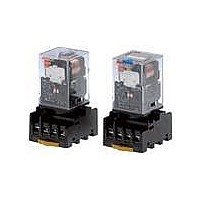
MKS2P DC24
Manufacturer Part Number
MKS2P DC24
Description
MKS Relay
Manufacturer
Omron
Series
MKSr
Datasheet
1.MKS2PI_DC110.pdf
(10 pages)
Specifications of MKS2P DC24
Contact Form
DPDT
Coil Voltage
24 VDC
Contact Rating
10 A
Contact Termination
Quick Connect
Mounting Style
Plug-In
Power Consumption
1.4 W
Contact Material
Silver Alloy
Coil Current
55.8 mA
Coil Resistance
430 Ohms
Lead Free Status / RoHS Status
Lead free / RoHS Compliant
Lead Free Status / RoHS Status
Lead free / RoHS Compliant


■ Characteristics
Note: 1. The values given above are initial values.
■ Approved Standards
UL Recognized (File No. E41515) - - Ambient Temp. = 40°C
Note: 10A UL ratings are with no load on the other contact set.
CSA Certified by
Engineering Data
■ Reference Data
Maximum Switching Power
280
Contact resistance
Operate time
Release time
Max. operating frequency
Insulation resistance
Dielectric strength
Insulation method
Impulse withstand voltage
Pollution degree
Rated insulation voltage
Vibration resistance
Shock resistance
Life expectancy
Min. permissible load
Ambient temperature
Ambient humidity
Weight
Coil ratings
6 to 110 VDC
6 to 240 VAC
2. Ambient temperature of models with LED indicator is −25 to 60°C.
N.O.
contact
N.C.
contact
General Purpose Relays
100
50
30
10
5
3
1
10
DC resistive
DC resistive load
NC contact
with NO contact
load with
10 A, 250 V AC 50/60 Hz (Resistive)
10 A, 30 V DC (Resistive)
7 A, 250 V AC 50/60 Hz (General Use)
10 A, 250 V AC 50/60 Hz (Resistive)
10 A, 30 V DC (Resistive)
7 A, 250 V AC 50/60 Hz (General Use)
Contact ratings
30
50
AC resistive load
with NC contact
100
AC resistive load
with NO contact
100 mΩ max.
AC: 20 ms max.
DC: 30 ms max.
20 ms max.(40 ms max. for built-in diode models)
Mechanical: 18,000 operations/hr (no load)
Electrical:1,800 operations/hr (at rated load)
100 MΩ min. (at 500 VDC)
2,500 VAC 50/60 Hz for 1 min. between coil and contacts
1,000 VAC 50/60 Hz for 1 min. between contacts of same polarity and terminals of the same polarity
2,500 VAC 50/60 Hz for 1 min. between current-carrying parts, non-current-carrying parts, and opposite
polarity
Basic insulation
4.5 kV between coil and contacts (with 1.2 × 50 μs impulse wave)
3.0 kV between contacts of different polarity (with 1.2 × 50 μs impulse wave)
3
250 V
Destruction:10 to 55 Hz, 1.5 mm double amplitude
Malfunction:10 to 55 Hz, 1.0 mm double amplitude
Destruction:1,000 m/s
Malfunction:100 m/s
Mechanical: 5,000,000 operations min.
Electrical:100,000 operations min.
10 mA at 1 VDC P level: λ
Operating: –40 to 60°C (with no icing or condensation)
Operating: 5% to 85%
Approx. 90 g
Switching voltage (V)
300
AC inductive
load
(p.f. = 0.4)
500 1.000
MKS
Operations
100,000
100,000
2
(approx. 10 G)
2
(approx. 100 G)
60
=0.1 x 10
IEC Standard/TUV Certification: IEC61810-1
(Certification No. R50104853)
Note: Maximum carrying current per TUV Certification is 9 A when
Rated Carry Current vs. Ambient Rated Temperature
Note: The lower limit of the ambient operating temperature for models
Coil ratings
6, 12, 24, 48,
100, 110 VDC
6, 12, 24, 100,
110, 200, 220,
240 VAC
-6
10
5
0
/ ops
−40
new MK-S relays are mounted in PF083A-E or PF113A-E
Sockets.
with built-in operation indicators is −25°C.
−20
UL derating curve
N.O.
contact
N.C.
contact
0
20
Ambient temperature (°C)
10 A, 250 V AC 50/60 Hz (Resistive)
10 A, 30 V DC (Resistive)
7 A, 250 V AC 50/60 Hz (General Use)
5 A, 250 V AC 50/60 Hz (Resistive)
5 A, 30 V DC (Resistive)
7 A, 250 V AC 50/60 Hz (General Use)
40
Contact ratings
60
80
Operations
100,000
100,000
Related parts for MKS2P DC24
Image
Part Number
Description
Manufacturer
Datasheet
Request
R

Part Number:
Description:
MKS2P Socket
Manufacturer:
Omron
Datasheet:

Part Number:
Description:
MKS Relay
Manufacturer:
Omron
Datasheet:

Part Number:
Description:
G6S-2GLow Signal Relay
Manufacturer:
Omron Corporation
Datasheet:
Part Number:
Description:
Compact, Low-cost, SSR Switching 5 to 20 A
Manufacturer:
Omron Corporation
Datasheet:
Part Number:
Description:
Manufacturer:
Omron Corporation
Datasheet: