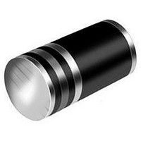
EGL34G-E3/98 Vishay, EGL34G-E3/98 Datasheet - Page 3

EGL34G-E3/98
Manufacturer Part Number
EGL34G-E3/98
Description
DIODE 0.5A 400V 50NS MELF
Manufacturer
Vishay
Datasheet
1.EGL34D-E383.pdf
(4 pages)
Specifications of EGL34G-E3/98
Diode Type
Standard
Voltage - Forward (vf) (max) @ If
1.35V @ 500mA
Voltage - Dc Reverse (vr) (max)
400V
Current - Average Rectified (io)
500mA
Current - Reverse Leakage @ Vr
5µA @ 400V
Speed
Fast Recovery =< 500ns, > 200mA (Io)
Reverse Recovery Time (trr)
50ns
Mounting Type
Surface Mount
Package / Case
DO-213AA, Mini Melf
Repetitive Reverse Voltage Vrrm Max
400V
Forward Current If(av)
500mA
Forward Voltage Vf Max
1.35V
Reverse Recovery Time Trr Max
50ns
Forward Surge Current Ifsm Max
10A
Product
Ultra Fast Recovery Rectifier
Configuration
Single
Reverse Voltage
400 V
Forward Voltage Drop
1.35 V
Recovery Time
50 ns
Forward Continuous Current
0.5 A
Max Surge Current
10 A
Reverse Current Ir
5 uA
Mounting Style
Through Hole
Maximum Operating Temperature
+ 175 C
Minimum Operating Temperature
- 65 C
Lead Free Status / RoHS Status
Lead free / RoHS Compliant
Capacitance @ Vr, F
-
Lead Free Status / Rohs Status
Details
Available stocks
Company
Part Number
Manufacturer
Quantity
Price
PACKAGE OUTLINE DIMENSIONS in inches (millimeters)
Document Number: 88580
Revision: 15-Mar-11
THE PRODUCT DESCRIBED HEREIN AND THIS DATASHEET ARE SUBJECT TO SPECIFIC DISCLAIMERS, SET FORTH AT
0.001
0.01
0.01
100
100
Fig. 3 - Typical Instantaneous Forward Characteristics
0.1
0.1
10
10
1
2
1
1
st
nd
0.2
0
band denotes type and polarity
band denotes voltage type
Pulse Width = 300 µs
1 % Duty Cycle
Percent of Rated Peak Reverse Voltage (%)
Fig. 4 - Typical Reverse Characteristics
0.4
1
st
Instantaneous Forward Voltage (V)
20
DO-213AA (GL34)
BAND
2
0.6
nd
Solderable Ends
BAND
T
0.022 (0.559)
0.016 (0.406)
0.145 (3.683)
0.131 (3.327)
J
0.8
= 150 °C
D2
40
DiodesAmericas@vishay.com, DiodesAsia@vishay.com,
1.0
For technical questions within your region, please contact one of the following:
T
J
= 150 °C
1.2
T
T
T
BYM07-50 thru BYM07-400, EGL34A thru EGL34G
J
J
J
60
EGL34A thru EGL34D
EGL34F and EGL34G
= 125 °C
= 75 °C
= 25 °C
1.4
T
J
1.6
= 25 °C
80
This datasheet is subject to change without notice.
1.8
D2 = D1
100
2.0
+ 0
- 0.008 (0.20)
0.049 (1.25)
100
0.1
35
30
25
20
15
10
10
5
0
1
MIN.
0.01
0.1
DiodesEurope@vishay.com
Fig. 6 - Typical Transient Thermal Impedance
Vishay General Semiconductor
Fig. 5 - Typical Junction Capacitance
0.1
Mounting Pad Layout
t - Pulse Duration (s)
Reverse Voltage (V)
1
0.177 (4.5) REF.
0.079 (2.0)
1
MAX.
www.vishay.com/doc?91000
10
T
f = 1.0 MHz
V
J
sig
10
= 25 °C
= 50 mV
www.vishay.com
p-p
0.079 (2.0)
100
100
MIN.
3


