184L Switchcraft Inc., 184L Datasheet - Page 305
184L
Manufacturer Part Number
184L
Description
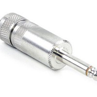
PHONE PLUG
Manufacturer
Switchcraft Inc.
Series
LITTEL-PLUG®r
Datasheet
1.184L.pdf
(333 pages)
Specifications of 184L
Rohs Information
Switchcraft RoHS Info.
Connector Type
Phone Plug
Gender
Male
Signal Lines
Mono
Plug/mating Plug Diameter
6.35mm (0.250", 1/4") - Headphone
Number Of Positions/contacts
2 Conductors, 2 Contacts
Internal Switch(s)
Does Not Contain Switch
Mounting Type
Free Hanging (In-Line)
Termination
Solder
Shielding
Shielded
Features
Cable Clamp
Standard
1/4 in
Termination Style
Solder
Contact Plating
Nickel
Color
Nickel
Contact Material
Copper Alloy
Mounting Style
Cable
Lead Free Status / RoHS Status
Lead free / RoHS Compliant
Color
-
Lead Free Status / Rohs Status
Lead free / RoHS Compliant
Available stocks
Company
Part Number
Manufacturer
Quantity
Price


300
w w w . s w i t c h c r a f t . c o m
SWITCHES
GENERAL PURPOSE STACK SWITCHES – COMPONENT SPECIFICATIONS
GENERAL PURPOSE STACK SWITCHES (continued)
GENERAL PURPOSE STACK SWITCHES – COMPONENT SPECIFICATIONS
STACK SWITCH COMPONENT SPECIFICATIONS
1. SPRINGS - Copper alloy in most standard gauge thickness-
es of .006" (0.15 mm), .008" (0.20 mm), .010" (0.25 mm), .012"
(0.30 mm), .016" (0.40 mm) and .020" (0.50 mm), a few designs
can be made up to .031" (.079 mm) thick. All or any contact
point hole can be provided; spring can be cut at any point.
2. BRACKETS - Standard brackets are detailed on drawing.
Tools are flexible so that various lengths from same width
stock can be provided.
3. LIFTERS OR PUSHERS - .125" (3.18 mm) and .188" (4.78
mm) diameter thermoplastic in various lengths staked into
one of the contact point holds provides tandem action
between blades or to serve as an actuator.
4. MOUNTING HARDWARE - Pressure plates (S1293 and
S2300) twin nuts (S1008 and S1431) and screws available for
mounting.
5. LEAF INSULATORS - Punched in same shape as springs
in .015" (0.38 mm) thickness of fish paper or mylar.
6. SPACERS - Rigid plastic is standard in thicknesses of .015"
(0.38 mm), .032" (0.81 mm), .051" (1.30 mm) and .062" (1.57
mm). Thickness of .093" (2.36 mm) is available for .375" (9.52
mm) mounting centers only. For longer surface creepage
paths, use both large and standard sized spacers. High tem-
perature insulation also available.
7. THERMOPLASTIC TUBING - .375" (9.52 mm) mounting
centers pass #5 screw. .250" (6.35 mm) mounting centers pass
#3 screw. .188" (4.78 mm) mounting centers pass #2 screw.
8. CAM FOLLOWERS - Two roller bracket designs (G1734
and G2298) available for springs .250" (6.35 mm) wide.
Copper alloy standard. Can be furnished in various diameters
and materials. Thermoplastic rollers also available.
9. CONTACTS - Welded cross bar contacts are commonly
used for cost savings. However, riveted contacts are available.
Size and material depend on circuit requirements (supply
complete details). For low level audio circuits, we suggest gold
alloy or palladium cross bar contacts. Springs can be
bifurcated (two contacts per spring).
TYPICAL STACK ASSEMBLY
DIMENSIONS ARE FOR REFERENCE ONLY
HOW TO ORDER STACK SWITCHES
Careful consideration of the following suggestions will help
specify the most economical and expeditious approach to your
switching needs. On initial inquiry or order, supply the following
information:
1. Simple sketch or drawing. See “Typical Stack Assembly”
2. Current, voltage and type of switching load (resistive or
3. Frequency of operation; life requirements.
4. Details of actuator.
5. Maximum and minimum movement of actuator blade.
6. Any other important specifying details.
It is recommended that data indicated above be forwarded to
Switchcraft for comments and recommendations before finalizing
your design.
drawing. Give details checked that are available.
inductive).
1.
2.
3.
4.
5.
(mm)
Note: Contact your Switchcraft Representative for price and delivery
Inch
PHONE: 773 792 - 2700
® Registered trademark of Switchcraft, Inc.
6.
7.
8.
9.
Related parts for 184L
Image
Part Number
Description
Manufacturer
Datasheet
Request
R

Part Number:
Description:
CONN PLUG PHONE 1/4" 2-COND
Manufacturer:
Switchcraft Inc.
Datasheet:

Part Number:
Description:
CONN PLUG PHONE 1/4" 2POS RED
Manufacturer:
Switchcraft Inc.
Datasheet:

Part Number:
Description:
CONN PLUG 2-COND 1/4" PHONE SLD
Manufacturer:
Switchcraft Inc.
Datasheet:

Part Number:
Description:
CONN PLUG PHONE SILENT 2-COND
Manufacturer:
Switchcraft Inc.
Datasheet:
Part Number:
Description:
THICK PANEL/GOLD PLA
Manufacturer:
Switchcraft Inc.
Datasheet:

Part Number:
Description:
CONN JACK PHONE 1/4" 2POS CLOSED
Manufacturer:
Switchcraft Inc.
Datasheet:

Part Number:
Description:
PHONE HI-D JACK .25" 2COND SLD
Manufacturer:
Switchcraft Inc.
Datasheet:

Part Number:
Description:
ADAPTER PHONO PLUG - A3M
Manufacturer:
Switchcraft Inc.
Datasheet:

Part Number:
Description:
SWITCH PB MOM RED PNL MT W/HDWR
Manufacturer:
Switchcraft Inc.
Datasheet:

Part Number:
Description:
SWITCH PB 1-CIR REAR MT BLACK
Manufacturer:
Switchcraft Inc.
Datasheet:
Part Number:
Description:
SWITCH PB MOM RED SPDT PANEL MNT
Manufacturer:
Switchcraft Inc.
Datasheet:
Part Number:
Description:
SWITCH PUSHB 1-A SLD LUG RED
Manufacturer:
Switchcraft Inc.
Datasheet:

Part Number:
Description:
SWITCH PB MOM PHONO JACK TERM
Manufacturer:
Switchcraft Inc.
Datasheet:

Part Number:
Description:
Pushbutton Switch,STRAIGHT,SPDT,ON-(ON),SOLDER Terminal
Manufacturer:
Switchcraft Inc.
Datasheet: