Z-15G-B Omron, Z-15G-B Datasheet - Page 16
Z-15G-B
Manufacturer Part Number
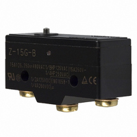
Z-15G-B
Description
BASIC SWITCH
Manufacturer
Omron
Series
Zr
Type
Snap Actionr
Datasheets
1.AP-B.pdf
(26 pages)
2.A6ER-4104.pdf
(14 pages)
3.Z-15HW24-B.pdf
(25 pages)
4.Z-15G-B.pdf
(15 pages)
Specifications of Z-15G-B
Microswitch Type
Standard
Actuator Style
Pin Plunger
Operating Force Max
350gf
Contact Voltage Ac Nom
250V
Contact Voltage Dc Nom
250V
Contact Current Max
15A
Switch Terminals
Screw
Circuit
SPDT
Switch Function
On-Mom
Contact Rating @ Voltage
15A @ 125VAC
Actuator Type
Round (Pin Plunger)
Mounting Type
Chassis Mount
Termination Style
Screw Terminal
Operating Force
350gf
Contact Form
SPDT
Contact Rating
15 Amps at 250 Volts
Actuator
Plunger, Pin
Post Position
Standard
Brand/series
Z Series
Current, Rating
15 A
Dielectric Strength
1000 VAC
Force, Operating
550 g
Ip Rating
IP00
Material, Casing
Phenolic Resin
Mounting Hole Size
4.2 mm
Number Of Poles
1
Operation
Snap Action
Standards
UL Listed, CSA Certified, CE Marked
Temperature Rating
-25 to +80 °C
Termination
Screw
Voltage, Rating
250 VAC
Pole Throw Configuration
SPDT
Switch Function Configuration
N.O./N.C.
Actuator Material
Stainless Steel
Current Rating (max)
15A
Ac Voltage Rating (max)
250VVAC
Dc Voltage Rating (max)
250VVDC
Contact Material
Silver
Mechanical Life
20000000
Terminal Type
Screw
Product Depth (mm)
17.45mm
Product Length (mm)
49.2mm
Operating Temp Range
-25C to 80C
Lead Free Status / RoHS Status
Lead free / RoHS Compliant
Lead Free Status / RoHS Status
Lead free / RoHS Compliant
Other names
SW190
Z-15G-B7-K
Z15G-B
Z15G-B7-K
Z15GB
Z15GB7K
Z-15G-B7-K
Z15G-B
Z15G-B7-K
Z15GB
Z15GB7K
Available stocks
Company
Part Number
Manufacturer
Quantity
Price


Note: 1. All drawings show the switches with screw terminals. For versions with solder terminals, remove the “-B” from the end of the part number.
162
Panel Mount Plunger
Z-15GQ55-B
Panel Mount Roller Plunger
Z-15GQ2255-B
Panel Mount Cross Roller Plunger
Z-15GQ2155-B
Leaf Spring
Z-15GL55-B
2. Unless otherwise specified, all units are in millimeters and a tolerance of ± 0.4 mm applies to all dimensions.
General-purpose Basic Switch
PT
OP
PT
OP
PT
OP
FP
13.1
16.3
15.5
16.3
15.5
16.3
OP
4.2
4.2
4.2
4.2
*3
*4
*3
+0.075
+0.075
+0.075
-0.025
-0.025
-0.025
+0.075
-0.025
*1. Stainless-steel plunger
*2. Two hexagonal nuts (2 t × 14 width across flats)
*3. Two lock nuts (2 t × 15.6 width across flats)
*4. Incomplete screw part with a maximum length of 1.5 mm.
*1. Stainless-steel roller
*2. Two hexagonal nuts (3 t × 17 width across flats)
*3. Incomplete screw part with a maximum length of 1.5 mm.
*1. Stainless-steel roller
*2. Two hexagonal nuts (3 t × 17 width across flats)
*3. Incomplete screw part with a maximum length of 1.5 mm.
49.6
16 dia.
16 dia.
16 dia.
Z
4.36
4.36
4.36
± 0.8
23.3
25.4
23.3
25.4
23.3
25.4
4.36
11.9SR
25.4
49.2
49.2
49.2
+0.1
+0.1
+0.1
49.2
-0.05
-0.05
-0.05
± 0.25
± 0.1
± 0.25
± 0.1
± 0.25
+0.1
± 0.1
-0.05
t = 0.3 *
± 0.1
*1
dia.
dia.
dia.
dia.
11.9
11.9
11.9
11.9
4.2
4.2
4.2
4.2
+0.075
+0.075
+0.075
-0.025
-0.025
-0.025
+0.075
-0.025
dia. hole
dia. hole
dia. hole
dia. hole
* Stainless-steel spring lever
17.45
17.45
17.45
8.35 dia.
17.45
4.8
± 0.2
± 0.2
± 0.2
12.7 dia. × 4.8 *1
± 0.2
12.7 dia. × 4.8 *1
M12 × 1
Mounting
screw
M12 × 1
mounting screw
M12 × 1
mounting
screw
9.2
9.2
9.2
*2
*2
9.2
*2
*3
23.9
Note: Do not use the M12
* When operating, be sure not
Note: Do not use the M12
OF max.
RF min.
PT max.
OT min.
MD max.
OP
Note: Do not use the M12
OF max.
RF min.
*OT min.
MD max.
FP max.
OP
OF max.
RF min.
PT max.
OT min.
MD max.
OP
OF max.
RF min.
PT max.
OT min.
MD max.
OP
to exceed 1.6 mm.
mounting screw and the
case mounting hole at
the same time, or the
case may be damaged.
mounting screw and the
case mounting hole at
the same time, or the
case may be damaged.
mounting screw and the
case mounting hole at
the same time, or the
case may be damaged.
21.8±0.8 mm
17.5±0.8 mm
33.4±1.2 mm
33.4±1.2 mm
0.06 mm
20.6 mm
3.58 mm
0.06 mm
1.8 mm
5.5 mm
3.58 mm
0.06 mm
1.6 mm
1.3 mm
1.8 mm
540 gf
114 gf
1.8 mm
200 gf
540 gf
114 gf
540 gf
114 gf
14 gf
Related parts for Z-15G-B
Image
Part Number
Description
Manufacturer
Datasheet
Request
R

Part Number:
Description:
BASIC SWITCH
Manufacturer:
Omron
Datasheet:

Part Number:
Description:
MICROSWITCH, PIN PLUNGER
Manufacturer:
Omron
Datasheet:
Part Number:
Description:
SWITCH SPDT 15A PNL ROLLR PLUNGR
Manufacturer:
Omron
Datasheet:
Part Number:
Description:
BASIC SWITCH
Manufacturer:
Omron
Datasheet:
Part Number:
Description:
BASIC SWITCH
Manufacturer:
Omron
Datasheet:

Part Number:
Description:
SWITCH, GENERAL PURPOSE, 15 AMP, SHORT ROLLER, 8.8-12.3 OF
Manufacturer:
Omron Automation
Datasheet:
Part Number:
Description:
SWITCH, GENERAL PURPOSE, 15 AMP, HINGE LEVER, 2.5 OF
Manufacturer:
Omron Automation
Datasheet:
Part Number:
Description:
SWITCH, GENERAL PURPOSE, 15 AMP, ROLLER LEVER, 8.8-12.3 OF
Manufacturer:
Omron Automation
Datasheet:
Part Number:
Description:
SWITCH, GENERAL PURPOSE, 15 AMP, SHORT SPRING PLUNGER, 18.9 OF
Manufacturer:
Omron Automation
Datasheet:
Part Number:
Description:
SWITCH, GENERAL PURPOSE, 15 AMP, SHORT SPRING PLUNGER, 8.8-12.3 OF
Manufacturer:
Omron Automation
Datasheet:
Part Number:
Description:
SWITCH, GENERAL PURPOSE, 15 AMP, CROSS ROLLER PLUNGER, 8.8-12.3 OF
Manufacturer:
Omron Automation
Datasheet:
Part Number:
Description:
SWITCH, GENERAL PURPOSE, 15 AMP, UNDIRECT SHORT ROLLER LEVER, .98 OF
Manufacturer:
Omron Automation
Datasheet:
Part Number:
Description:
SWITCH, GENERAL PURPOSE, 15 AMP, HINGE LEVER, 3.5 OF
Manufacturer:
Omron Automation
Datasheet: