X-10G-B Omron, X-10G-B Datasheet - Page 2
X-10G-B
Manufacturer Part Number
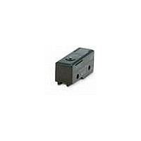
X-10G-B
Description
BASIC SWITCH
Manufacturer
Omron
Series
Xr
Specifications of X-10G-B
Circuit
SPDT
Switch Function
On-Mom
Contact Rating @ Voltage
10A @ 30VDC
Actuator Type
Round (Pin Plunger)
Mounting Type
Chassis Mount
Termination Style
Screw Terminal
Operating Force
510gf
Pole Throw Configuration
SPDT
Switch Function Configuration
N.O./N.C.
Actuator Style
Pin Plunger
Actuator Material
Stainless Steel
Current Rating (max)
10A
Dc Voltage Rating (max)
250VVDC
Contact Material
Silver
Mechanical Life
1000000
Terminal Type
Screw
Product Depth (mm)
17.45mm
Product Length (mm)
49.2mm
Operating Temp Range
-25C to 80C
Contact Form
SPDT
Contact Rating
10 Amps at 125 Volts
Actuator
Plunger, Pin
Lead Free Status / RoHS Status
Lead free / RoHS Compliant
Lead Free Status / RoHS Status
Lead free / RoHS Compliant
Other names
X10GB


Specifications
Ratings
Note: 1. The above values are for the steady-state current.
Certified Standard Ratings
Ask your OMRON representative for information on certified models.
UL/CSA
EN (CE)
Characteristics
*1. The values are for the pin plunger models. (Contact your OMRON
*2. Malfunction: 1 ms max.
Structure
Contact Form (SPDT)
Note: With the reverse-type models (X-10GM@), the NC and NO terminal arrangements are reversed.
8 VDC
14 VDC
30 VDC
125 VDC
250 VDC
Rated voltage
Rated voltage
Operating speed
Operating
frequency
Insulation resistance
Contact resistance
Dielectric strength
Vibration
resistance
Shock
resistance
Durability
Degree of protection
Degree of protection
against electric shock
Proof tracking index (PTI)
Ambient operating
temperature
Ambient operating
humidity
Weight
representative for other models.)
voltage
Rated
2. Inductive load has a power factor of 0.4 min. (AC) and a time constant
3. Lamp load has an inrush current of 10 times the steady-state current.
4. Motor load has an inrush current of 6 times the steady-state current.
5. The above electrical ratings also apply to the AC voltage.
6. With the reverse-type models (X-10GM@), the normally closed circuits
7. The ratings values apply under the following test conditions:
of 7 ms max. (DC).
and normally open circuits are reversed.
(1) Ambient temperature: 20±2°C
(2) Ambient humidity: 65±5%RH
(3) Operating frequency: 20 operations/min
(+) COM
(Conform to EN61058-1)
125 VDC
250 VDC
125 VDC
Mechanical
Electrical
Malfunction
Destruction
Malfunction
Mechanical
Electrical
NC
Resistive
Non-inductive load (A)
load
10
10
10
10
3
Model
Model
NO
Lamp load
NC
1.5
0.1 mm to 1 m/s *1
240 operations/min
20 operations/min
100 MΩ min. (at 500 VDC)
15 mΩ max. (initial value)
1,500 VAC, 50/60 Hz for 1 min between
terminals of the same polarity, between
current-carrying metal parts and the ground,
and between each terminal and non-current-
carrying metal parts
10 to 55 Hz, 1.5-mm double amplitude *2
1,000 m/s
300 m/s
1,000,000 operations min.
100,000 operations min.
IP00
Class I
175
−25°C to 80°C (with no icing)
35% to 85%RH
Approx. 27 to 63 g
3
3
3
3
NC
NO
0.75
NO
1.5
1.5
1.5
1.5
2
max. *1 *2
2
max.
NC
7.5
10
10
10
Inductive
2
X-10G
load
10 A
X-10
10 A
Inductive load (A)
3 A
NO
1.5
10
10
10
6
Motor load
NC
5
5
5
5
2
NO
2.5
2.5
2.5
2.5
1.5
Contact Specification
Engineering Data
Mechanical Durability (X-10G)
Electrical Durability (X-10G)
Contacts
Inrush current
5,000
3,000
1,000
500
300
200
100
70
50
30
20
10
700
500
300
200
100
7
5
3
2
1
70
50
30
20
10
0
0
125 VDC
L/R = 7 ms
0.1
2
Ambient temperature: 20±2°C
Ambient humidity: 65±5%RH
Without load
Operating frequency: 240 operations/min
0.2
Ambient temperature: 20±2°C
Ambient humidity: 65±5%RH
Operating frequency: 20 operations/min
4
0.3
Material
Gap
(standard value)
NC
NO
0.4
6
125 VDC L/R = 0
0.5
8
Switching current (A)
0.6
Overtravel (mm)
10
0.7
12
0.8
0.9
14
30 A max.
15 A max.
0.9 mm
Silver
X
2
Related parts for X-10G-B
Image
Part Number
Description
Manufacturer
Datasheet
Request
R

Part Number:
Description:
Basic / Snap Action / Limit Switches BASIC SWITCH
Manufacturer:
Omron
Datasheet:

Part Number:
Description:
BASIC SWITCH
Manufacturer:
Omron
Datasheet:

Part Number:
Description:
SWITCH LEVER SPDT 10A SCREW
Manufacturer:
Omron
Datasheet:
Part Number:
Description:
BASIC SWITCH
Manufacturer:
Omron
Datasheet:
Part Number:
Description:
Basic / Snap Action / Limit Switches BASIC SWITCH
Manufacturer:
Omron
Datasheet: