VX-54-1A3 Omron, VX-54-1A3 Datasheet - Page 6
VX-54-1A3
Manufacturer Part Number
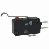
VX-54-1A3
Description
MINIATURE BASIC SWITCH
Manufacturer
Omron
Series
VXr
Type
Snap Actionr
Specifications of VX-54-1A3
Circuit
SPDT
Switch Function
On-Mom
Contact Rating @ Voltage
5A @ 250VAC
Actuator Type
Lever, Simulated Roller
Mounting Type
Chassis Mount
Termination Style
Solder, Quick Connect - .187" (4.7mm)
Operating Force
30gf
Contact Form
SPDT
Contact Rating
5 Amps
Actuator
Simulated Roller Lever
Body Style
Miniature
Current, Rating
5 A
Dielectric Strength
1500 VAC
Mounting Hole Size
3.1 mm
Number Of Poles
1
Operation
Snap Action
Termination
Solder/Quick Connect
Voltage, Rating
125/30 VAC/VDC
Pole Throw Configuration
SPDT
Switch Function Configuration
N.O./N.C.
Actuator Style
Sim Roller Lever
Current Rating (max)
5A
Ac Voltage Rating (max)
250VVAC
Dc Voltage Rating (max)
250VVDC
Contact Material
Silver Alloy
Mechanical Life
50000000
Terminal Type
Solder
Product Height (mm)
28mm
Product Depth (mm)
10.3mm
Product Length (mm)
48.9mm
Operating Temp Range
-25C to 80C
Lead Free Status / RoHS Status
Lead free / RoHS Compliant
Lead Free Status / RoHS Status
Lead free / RoHS Compliant
Other names
SW998
VX-54-1A3
VX541A3
VX-54-1A3
VX541A3


VX
Precautions
Refer to General Information.
■
Handling
Be careful not to drop the Switch. Doing so may cause damage to
the Switch’s internal components because it is designed for a
small load.
■
Mounting
Use M3 mounting screws with plane washers or spring washers
to securely mount the Switch. Tighten the screws to a torque of
0.39 to 0.59 N·m {4 to 6 kgf·cm}.
Mounting Direction
For a Switch with an actuator, mount the Switch in a direction
where the actuator weight will not be applied to the Switch.
Since the Switch is designed for a small load, its resetting force is
small. Therefore, resetting failure may occur if unnecessary load
is applied to the Switch.
6
Short Hinge Roller Lever Models
Hinge Roller Lever Models
Cautions
Correct Use
OP
PT
PT
OP
3.4±0.15 dia.
2.8
2.8
3.4±0.15 dia.
3.1
t = 0.5 (stainless-steel lever)
3.1
+0.13
10.3±0.1
−0.03
A
+0.13
10.3±0.1
−0.03
t = 0.5 (stainless-steel lever)
A
22.2±0.1
34.0±0.8
27.8
22.2±0.1
37.8±0.8
27.8
20.1
37.8±0.8
8.1
8.1
(10)
1.6
2.8
3.1
(10)
4.8 dia. × 4.8 (oilless polyacetar resin roller)
3.1
1.6
2.8
+0.13
−0.03
Three, solder terminals
+0.13
−0.03
15.9 18.8
Three, solder terminals
dia. holes
15.9 18.8
dia. holes
4.8 dia. × 4.8
(oilless polyacetar resin roller)
Using Micro Loads
Using a model for ordinary loads to open or close the contact of a
micro load circuit may result in faulty contact. Use models that
operate in the following range. However, even when using micro
load models within the operating range shown below, if inrush
current occurs when the contact is opened or closed, it may
increase contact wear and so decrease durability. Therefore,
insert a contact protection circuit where necessary.
The minimum applicable load is the N-level reference value. This
value indicates the malfunction reference level for the reliability
level of 60% (λ 60). The equation, λ 60 = 0.5×10
indicates that the estimated malfunction rate is less than 1/
2,000,000 operations with a reliability level of 60%.
10.3
5.1
10.3
Inoperable
range
5.1
Operating range
for micro load
models VX-01
OF max.
RF min.
PT max.
OT min.
MD max.
OP
Note:
OF max.
RF min.
PT max.
OT min.
MD max.
OP
Model
Model
The values indicated in parentheses
are reference values for cases when
the installation direction is such that
the lever weight is not applied to the
plunger.
0.29 N {30 gf}
---
4.0 mm
1.6 mm
0.8 mm
20.7±1.2 mm
0.59 N {60 gf}
0.04 N {4 gf} (reference value)
1.6 mm
0.8 mm
0.5 mm
20.7±0.6 mm
VX-56-1@3
VX-55-1@3
Current (mA)
Operating
range for
general-
load models
VX-5
VX-016-1@3
VX-015-1@3
–6
/operations
VX
Related parts for VX-54-1A3
Image
Part Number
Description
Manufacturer
Datasheet
Request
R

Part Number:
Description:
MINIATURE BASIC SWITCH
Manufacturer:
Omron
Datasheet:


Part Number:
Description:
MINIATURE BASIC SWITCH
Manufacturer:
Omron
Datasheet:

Part Number:
Description:
MINIATURE BASIC SWITCH
Manufacturer:
Omron
Datasheet:

Part Number:
Description:
MINIATURE BASIC SWITCH
Manufacturer:
Omron
Datasheet:
Part Number:
Description:
MINIATURE BASIC SWITCH
Manufacturer:
Omron
Datasheet:

Part Number:
Description:
MINIATURE BASIC SWITCH
Manufacturer:
Omron
Datasheet:

Part Number:
Description:
MINIATURE BASIC SWITCH
Manufacturer:
Omron
Datasheet:

Part Number:
Description:
MINIATURE BASIC SWITCH
Manufacturer:
Omron
Datasheet:

Part Number:
Description:
MINIATURE BASIC SWITCH
Manufacturer:
Omron
Datasheet:

Part Number:
Description:
MINIATURE BASIC SWITCH
Manufacturer:
Omron
Datasheet:

Part Number:
Description:
MINIATURE BASIC SWITCH
Manufacturer:
Omron
Datasheet:
Part Number:
Description:
MINIATURE BASIC SWITCH
Manufacturer:
Omron
Datasheet: