SSG-5L1H-5 Omron, SSG-5L1H-5 Datasheet - Page 7
SSG-5L1H-5
Manufacturer Part Number
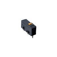
SSG-5L1H-5
Description
Subminiature Basic Switch
Manufacturer
Omron
Series
SSGr
Datasheet
1.SSG-5H.pdf
(8 pages)
Specifications of SSG-5L1H-5
Circuit
SPDT
Switch Function
On-Mom
Contact Rating @ Voltage
5A @ 125VAC
Actuator Type
Lever, Straight
Mounting Type
Chassis Mount
Termination Style
Solder Lug
Operating Force
20gf
Actuator
Lever
Contact Form
SPDT
Contact Rating
5 Amps at 125 Volts, 4 Amps at 30 Volts
Lead Free Status / RoHS Status
Lead free / RoHS Compliant
Lead Free Status / RoHS Status
Lead free / RoHS Compliant
Other names
SSG5L1H5


Precautions
Be sure to read the precautions and information common to all Snap Action and Detection Switches, contained in the Technical User’s Guide,
“Snap Action Switches, Technical Information” for correct use.
■ Correct Use
Mounting
Mount the switch onto a flat surface. Mounting on an uneven surface
may cause deformation of the switch, resulting in faulty operation or
breakage in the housing.
Operating Stroke
Make sure that the operating stroke is 70% to 100% of the rated OT
distance. Do not operate the actuator exceeding the OT distance,
otherwise the life expectancy of the switch may be shortened.
Using Microloads
Using a model for ordinary loads to switch microloads may result in
faulty operation. Instead, use the models that are designed for
microloads and that operate in the following range;
However, even when using microload models within the operating
range shown above, if inrush current or inductive voltage spikes
occur when the contact is opened or closed, then contact wear may
increase and so decrease the service life. Therefore, insert a contact
protection circuit where necessary.
■ Cautions
Handling
Turn OFF the power supply before mounting or removing the switch,
wiring, or performing maintenance for inspection. Failure to do so
may result in electric shock or burning
Terminal Connection
When soldering the lead wire to the terminal, first insert the lead wire
conductor through the terminal hole and then solder.
Make sure that the capacity of the soldering iron is 60 W maximum.
Do not take more than 5 seconds to solder the switch terminal.
Improper soldering involving an excessively high temperature or
excessive soldering time may deteriorate the characteristics of the
switch.
Be sure to apply only the minimum required amount of flux. The
switch may have contact failures if flux intrudes in the interior of the
switch.
Use the following lead wires to connect to the solder terminals;
To automatically solder the Switch to a PCB in a soldering bath, com-
plete soldering within 5 seconds at a flux temperature of 250°C and
avoid the overflow of flux onto the surface of the PCB where the
Switch or other parts are mounted.
Wire the quick-connect terminals (#110) with receptacles. Insert the
terminals straight into the receptacles. Do not impose excessive
force on the terminal in the horizontal direction, otherwise the termi-
nal may be deformed or the housing may be damaged.
Insulation Distance
Use a separator between the switch and metal mounting panels, to
ensure proper dielectric characteristics are achieved.
The Switch does not have a ground terminal. The minimum distance
through insulation (IEC61058-1) is 0.9 mm. If proper insulation for
the end product cannot be secured, additional insulation such as a
Separator or insulation cover should be attached.
Subminiature Basic Switch
SSG-01
SSG-5
Model
Conductor size
AWG 22 to 20
AWG 20 to 18
SSG
115
Related parts for SSG-5L1H-5
Image
Part Number
Description
Manufacturer
Datasheet
Request
R

Part Number:
Description:
SWITCH SUBMINI SPDT 5A PIN PLNGR
Manufacturer:
Omron
Datasheet:

Part Number:
Description:
SWITCH SUBMINI SPDT 5A HINGE LVR
Manufacturer:
Omron
Datasheet:
Part Number:
Description:
SWITCH SUBMINI SPDT 5A PIN PLNGR
Manufacturer:
Omron
Datasheet:
Part Number:
Description:
SWITCH SUBMINI SPDT 5A PIN PLNGR
Manufacturer:
Omron
Datasheet:
Part Number:
Description:
SWITCH SUBMINI SPDT 5A HINGE LVR
Manufacturer:
Omron
Datasheet:
Part Number:
Description:
SWITCH SUBMINI SPDT 5A ROLL LEVR
Manufacturer:
Omron
Datasheet:
Part Number:
Description:
SWITCH SUBMINI SPDT 5A ROLL LEVR
Manufacturer:
Omron
Datasheet:
Part Number:
Description:
Subminiature Basic Switch
Manufacturer:
Omron
Datasheet:
Part Number:
Description:
SUBMINIATURE BASIC SWITCH
Manufacturer:
Omron
Datasheet:
Part Number:
Description:
SUBMINIATURE BASIC SWITCH
Manufacturer:
Omron
Datasheet:
Part Number:
Description:
Subminiature Basic Switch
Manufacturer:
Omron
Datasheet:
Part Number:
Description:
Subminiature Basic Switch
Manufacturer:
Omron
Datasheet:
Part Number:
Description:
SUBMINIATURE BASIC SWITCH
Manufacturer:
Omron
Datasheet:
Part Number:
Description:
Subminiature Basic Switch
Manufacturer:
Omron
Datasheet:
Part Number:
Description:
Subminiature Basic Switch
Manufacturer:
Omron
Datasheet: