P2R-05A Omron, P2R-05A Datasheet
P2R-05A
Specifications of P2R-05A
P2R05A
Z2283


Related parts for P2R-05A


P2R-05A Summary of contents
Page 1
... Relay Type G7J-(ALL) G7L-1A-T G7L-1A-TJ G7L-1A-B G7L-1A-BJ G7L-2A-T G7L-2A-TJ G7L-2A-B G7L-2A-BJ 238 General-purpose Relays and Power Relays Track Mount Sockets Solder terminals P2RF-05 P2R-05A P2RF-05-E P2RF-05-S P2RF-08 P2R-08A P2RF-08-E P2RF-08-S PTF08A-E PT08 PTF11A PT11 PTF14A-E PT14 PFO83A-E PL08 PF113A-E PL11 ...
Page 2
... PYF08A PY08 Approx Approx PY08-Y1 PYF08A-E PYF08A-N PY08-Y3 Note: @-E and @-N Models are of finger-protect construction. Round terminals cannot be used. Use Y-shaped terminals. *see page 248 Solder terminal P2R-05P P2R-05A Approx Approx P2R-08P P2R-08A Approx Approx PTF (back-connecting) (Track- *see page 252 mounting) ...
Page 3
Item PYF (Track- mounting) *see page 250 Screw terminal Solder terminal 11 pins PYF11A PY11 Approx Approx PY11-Y1 14 pins PYF14A PY14 Approx Approx PY14-Y1 PYF14A-E PYF14A-N PY14-Y2 PYF14T Approx ...
Page 4
Round Sockets Item PF P2CF (Track- (Track- mounting) mounting) *see page 258 8 pins PF083A P2CF-08 Approx Approx PF083A-E PF085A Approx pins PF113A P2CF-11 Approx Approx PF113A-E 14 pins ...
Page 5
Hold-down Clips For Square Sockets PYC-A1 PYC-A2 (see note) (see note) 5 max. 5 max. 36.3 42.8 4.5 4.5 1.2 4.5 1.2 4.5 PYC-P2 PYC 2.5 PYC 10 3.7 34.5 For Round Sockets PEC-A6 PFC-A1 (see ...
Page 6
Models Used with Sockets Group MY(K) MY2 MY3 MY4, MY2K LY LY1, LY2 LY3 LY4 G2A(K) G2A, G2A-434, G2AK MK(K) MK2P MK3P, MK2KP MM(K) MM2(X)P MM3P, MM2(X)KP MM3XP, MM3(X)KP, MM4(X)P, MM4(X)KP G4Q --- G7L G7L-@A-T(J) ■ Models Used with ...
Page 7
... Socket Performance Characteristics Item Carry current P2RF-05(- P2RF-08(- P2R-057P 10 A P2R-087P 5 A P2R-05A 10 A P2R-08A 5 A P7TF- PYF08A PYF08A (see note 3) PYF11A 5 A PYF14A PYF14A (see note 3) PY08(-Y1 PY08QN(-Y1 PY08- PY11(-Y1 PY11QN(-Y1 PY11- PY14(-Y1 PY14QN(-Y1 PY14- PTF@@ PT PT@@ PT@@- 244 General-purpose Relays and Power Relays ...
Page 8
Item Carry current P7LF- PF@@@ P2CF 5 A P3G( 8PFA( 11PFA( PL@@(- PLE@@- P6D-04P 5 A P7S-14 Note: 1. The values given above are ...
Page 9
... Dimensions P2RF-05 (One pole) Five, M3 71.5 max. 19.5 max. P2RF-05-E (One pole) M3.5 screw 3.5-dia. holes 85.5 max. * When mounted on H3RN-1@. P2RF-08 (Two poles) Eight, M3 71.5 max. 19.5 max. 246 General-purpose Relays and Power Relays Terminal arrangement/Internal connections (top view) 4 dia. ...
Page 10
... Dimensions P2RF-08-E (Two poles) M3 screw 3.5-dia. holes 85.5 max. * When mounted on H3RN-2@. Note: When indicator modules with an I/O SSR are used, the No. 1 pin becomes positive. Terminal arrangement/ Internal connections (top view) 63 max. (84.9 max.)* 48 max. 3 dia. Note: Figures in paren- theses are DIN 61 max ...
Page 11
... P2R-08P (Two poles) 14.5 max. 35.5 max. 36.5 max. P2R-057P (One pole) 14 max. 37 max. P2R-087P (Two poles) 14 max. 37 max. Note: When indicator modules with an I/O SSR are used, the No. 1 pin becomes positive. 248 General-purpose Relays and Power Relays arrangement/ Internal connections (bottom view) 36 ...
Page 12
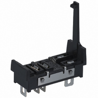
... P2R/P7TF Dimensions P2R-05A (One pole) 14.5 max. 35.5 max. 36.5 max. P2R-08A (Two poles) 14.5 max. 35.5 max. P7TF-05 19 max. Screw with square washer 71.5 max. Note: When indicator modules with an I/O SSR are used, the No. 1 pin becomes positive. ...
Page 13
PYF Dimensions Dimensions PYF08A Two, 4 mounting holes 72 max. 23 max. Two, 4 PYF08A-E mounting holes 6 72 max. 23 max. PYF08A-N 22 max ...
Page 14
Dimensions PYF14A Two, 4 mounting holes Fourteen sems 72 max. 29.5 max. PYF14A-E Two, 4 Fourteen, mounting holes sems 72 max. 29.5 max. PYF14A ...
Page 15
PY Dimensions Dimensions PY08 PY08-Y1 Eight, 3-dia. x 1.2 ellipses PY08- 2.7 42 max. 20 max. Note: PY08-Y1 includes the part outlined by the dashed lines above. PY08QN PY08QN2 PY08QN-Y1 PY08QN2- (20) 2 ...
Page 16
Dimensions PY14 PY14-Y1 (l=42 max.) PY14-Y3 (l=60 max.) Fourteen, 3-dia. x 1.2 ellipses * 20 max. l Note: PY14-Y1 includes the part outlined by the dashed lines above. PY14QN, PY14QN2 PY14QN-Y1 (l=42 max.) PY14QN2-Y1 (l=42 max.) PY14QN-Y2 (l=49 max.) PY14QN2-Y2 ...
Page 17
Dimensions PTF08A-E Two, 4 mounting holes 7 Eight, M3 sems 78.5 max. 28.5 max. PTF11A Two, 4 mounting holes 78.5 max. 37 max. PTF14A Two, 4 mounting holes 78.5 max. 45.5 max. ...
Page 18
PT Dimensions Dimensions PT08 PT08QN 5 0.3 9 25.5 29.5 max. max. 2.5 2.7 35 max. 2.7 Eight, 1.7-dia. x 3.5 ellipses 20.5 max. PT08 4.3 22 max. 18 max. *Keep a proper distance ...
Page 19
Dimensions PT14 PT14QN Fourteen, 1.7-dia. x 3.5 holes 42.5 max. 35 max. 26.5 max. 29.5 20.5 max. max. PT14-0 5* 26.5 max. 17.5 max. 29.5 max. *Keep a proper distance between the Socket and PCB patterns. Note: Use a panel ...
Page 20
P7S Dimensions Dimensions P7S-14F Fourteen, M3.0 40 max. 90.5 max. P7S-14A 61.5 max. 23 max. 33 max. P7S-14P 61.5 max. 23 max. Two, 6.5 dia. 7.9 29 max. Terminal arrangement/ Internal connections 47 max. 40 max. G7S-4A2B G7S-3A3B (bottom ...
Page 21
PF Dimensions Dimensions Eight, M3 PF083A sems screws 7 Two 4.2-dia. holes 52 max max. PF083A-E Eight, M3 sems Two, 4.2-dia. holes 52 max max. PF085A Eight, ...
Page 22
Dimensions PF202 101 max. Two, 4.5-dia. holes 71 max. Two, M3 Relay mounting screws Note: The key groove of PF083A and PF113A (used with MK Relays) are on the upside. ■ P2CF/PFA Dimensions Dimensions P2CF-08 Eight, M3.5 x 7.5 sems ...
Page 23
Dimensions 8PFA Eight, M3 sems screws Two, 4.5-dia. holes 81 max. 51 max. 8PFA1 Eight, M3 sems screws Two, 4.5-dia. holes 93 max. 51 max. ■ PFA/P3G/P3GA Dimensions Dimensions 11PFA Eleven, M3 sems screws ...
Page 24
Dimensions P3G-08 27 dia. P3GA-11 27 dia. ■ PL Dimensions Dimensions PL08 3.5 51 max max. PL08-Q 3.5 50.5 max max. PLE08-0 29 dia. 0.3 Note: When mounting, pay due attention to the direction of the ...
Page 25
PL Dimensions Dimensions PL11 30 dia. 51 max. 35 max. Approx. 20.5 max. PL11-Q 51 max. 35 max. 35 max. PLE11-0 29 0.1 dia. 22 max. PL15 66 max. 41 max. 45 max. 22 max. PL20 Two, 3.5-dia. holes ...
Page 26
... Please read and understand this catalog before purchasing the products. Please consult your OMRON representative if you have any questions or comments. WARRANTY OMRON's exclusive warranty is that the products are free from defects in materials and workmanship for a period of one year (or other period if specified) from date of sale by OMRON. OMRON MAKES NO WARRANTY OR REPRESENTATION, EXPRESS OR IMPLIED, REGARDING NON-INFRINGEMENT, MERCHANTABILITY, OR FITNESS FOR PARTICULAR PURPOSE OF THE PRODUCTS ...
Page 27
... São Paulo, SP, Brasil • 55.11.2101.6300 • www.omron.com.br OMRON ELECTRONICS MEXICO • HEAD OFFICE Apodaca, N.L. • 52.811.156.99.10 • 001.800.556.6766 • mela@omron.com OMRON EUROpE B.V. Wegalaan 67-69, NL-2132 JD, Hoofddorp, The Netherlands. Tel: +31 (0) 23 568 13 00 Fax: +31 (0) 23 568 13 88 www.industrial.omron.eu J35I-E-01 01/07 OMRON ARGENTINA • ...