M2BJ-B24B Omron, M2BJ-B24B Datasheet - Page 20
M2BJ-B24B
Manufacturer Part Number
M2BJ-B24B
Description
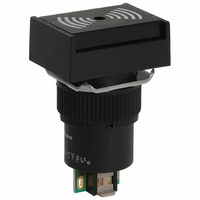
BUZZER
Manufacturer
Omron
Series
M2BJ-Br
Type
Audible Signal Devicer
Specifications of M2BJ-B24B
Frequency
4kHz
Voltage - Rated
12 ~ 24VAC/DC
Current Rating
20mA
Size / Dimension
Rectangular - 22mm L x 18mm W x 28.5mm H
Mounting Type
Panel Mount
Sound Pressure Level
80dB
Operating Mode
Continuous/Intermittent
Voltage Range
12 ~ 24VAC/DC
Termination
Solder Tab (s)
Illumination
Not Illuminated
Height
18 mm
Length
38 mm
Mounting Style
Panel
Termination Style
Solder
Width
22 mm
Lead Free Status / RoHS Status
Lead free / RoHS Compliant
Capacitance @ Frequency
-
Lead Free Status / Rohs Status
Lead free / RoHS Compliant
For Use With
A16 Series
Lead Free Status / RoHS Status
Lead free / RoHS Compliant
Other names
M2BJ-B24B
M2BJB24B
M3BJB24B
Z2747
M2BJB24B
M3BJB24B
Z2747
Available stocks
Company
Part Number
Manufacturer
Quantity
Price

Part Number:
M2BJ-B24B
Manufacturer:
OMRON/欧姆龙
Quantity:
20 000


Installation
J MOUNTING
After mounting the Pushbutton Unit to the panel, snap in the
Socket Unit from the back of the panel.
Panel mounting
Insert the Pushbutton Unit into the front of the panel, and fix the
lock ring and mounting nut from the terminal side.
Make sure that the lock ring is aligned with the thread of the case
and the edge of the lock ring is touching the panel.
Tighten the mounting nuts to a torque of 0.20 to 0.39 N • m (3 to
5 kgf • cm).
The maximum tightening torque is 0.39 N • m (5 kgf • cm).
Switch Mounting
Snap on the Switch Unit to the Pushbutton Unit.
Make sure the the Switch Unit is in the proper orientation when
snapping on to the Pushbutton Unit.
J SWITCH REMOVAL
Grip the part between the Switch holder of the case and the
Switch Unit using the A16Z-5080 Extractor, and pull to remove
the Switch Unit.
Case
A16Z-5080 Extractor
Edge
Thread
Panel
Lock ring
Mounting nut
21
J REPLACEMENT PARTS
Removal and installation of the Operating Part
J REMOVING THE LAMP
Removing from the Operating Part End
Removing from the Switch Unit End
The Lamp can be removed by hand once the Switch is removed
using the A16Z-5080 Extractor.
J INSTALLING THE LAMP
When mounting the Lamp, make sure it is facing the direction
shown in the following diagram. Insert the Lamp while matching
the protruding part of the Lamp and the small guides on the outer
surface of the case.
The Lamp can be mounted from the operating part end by using
the A16Z-5080 Extractor. The lamp can be mounted by following
the opposite procedure for removing the Lamp.
Protruding part
1. Remove the operating part as shown in the following
2. To attach the operating part, push until it clicks into place.
diagram. If the operating part cannot be removed by hand,
use the A3PJ-5080 Extractor.
Lamp
Grip the Lamp with the
A16Z-5080 Extractor and
pull to remove.
Operating section
Related parts for M2BJ-B24B
Image
Part Number
Description
Manufacturer
Datasheet
Request
R

Part Number:
Description:
BUZZER 12-24VDC CONT SOUND
Manufacturer:
Omron
Datasheet:

Part Number:
Description:
BUZZER 6 VAC/DC STANDARD SOUND
Manufacturer:
Omron
Datasheet:
Part Number:
Description:
BUZZER 6 VAC/DC STANDARD SOUND
Manufacturer:
Omron
Datasheet:
Part Number:
Description:
BUZZER 6 VAC/DC STANDARD SOUND
Manufacturer:
Omron
Datasheet:
Part Number:
Description:
BUZZER 6 VAC/DC STANDARD SOUND
Manufacturer:
Omron
Datasheet:
Part Number:
Description:
Buzzer
Manufacturer:
Omron
Datasheet:
Part Number:
Description:
BUZZER 6 VAC/DC HIGH SOUND
Manufacturer:
Omron
Datasheet:
Part Number:
Description:
BUZZER 6 VAC/DC HIGH SOUND
Manufacturer:
Omron
Datasheet:

Part Number:
Description:
G6S-2GLow Signal Relay
Manufacturer:
Omron Corporation
Datasheet:
Part Number:
Description:
Compact, Low-cost, SSR Switching 5 to 20 A
Manufacturer:
Omron Corporation
Datasheet:
Part Number:
Description:
Manufacturer:
Omron Corporation
Datasheet: