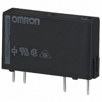
G6DS-1A-H DC12 Omron, G6DS-1A-H DC12 Datasheet - Page 3

G6DS-1A-H DC12
Manufacturer Part Number
G6DS-1A-H DC12
Description
Power PCB Relay
Manufacturer
Omron
Series
G6DSr
Datasheet
1.G6DS-1A-H_DC12.pdf
(8 pages)
Specifications of G6DS-1A-H DC12
Relay Type
General Purpose
Contact Form
SPST-NO (1 Form A)
Contact Rating (current)
5A
Switching Voltage
250VAC, 30VDC - Max
Coil Type
Standard
Coil Current
10mA
Coil Voltage
12VDC
Turn On Voltage (max)
8.4 VDC
Turn Off Voltage (min)
0.6 VDC
Mounting Type
Through Hole
Termination Style
PC Pin
Circuit
SPST-NO (1 Form A)
Contact Rating @ Voltage
5A @ 30VDC
Control On Voltage (max)
8.4 VDC
Control Off Voltage (min)
0.6 VDC
Lead Free Status / RoHS Status
Lead free / RoHS Compliant
Other names
G6DS-1A-H-DC12
G6DS1AHDC12
Z2321
G6DS1AHDC12
Z2321
Engineering Data
■ Approved Standards
• The rated values approved by each of the safety standards may be different from the performance characteristics individually defined in this catalog.
UL Recognized (File No. E41515) / CSA Certified (File No. LR31928) - - Ambient Temp. = 95°C
VDE (EN61810-1) (License No. B161)
G6DS-1A
G6DS-1A-H
G6DS-1A
G6DS-1A-H
Maximum Switching Power
Ambient Temperature vs.
Operating/Recovery Voltage
G6DS-1A
0.5
0.3
0.1
50
30
10
90
80
70
60
50
40
30
20
10
5
3
1
0
−60
0
−40
3
DC resistive
load
DC inductive
load
5
−20
Model
Model
10
0
Ambient temperature (°C)
30
Switching voltage (V)
20
AC inductive
load
cosφ=0.4
40
AC resistive load
100
60
250 500 1,000
SPST-NO
SPST-NO
80
max.
max.
min.
min.
ave.
ave.
Contact form
100
Contact form
Endurance
Malfunctioning Shock
G6DS-1A
500
300
100
50
30
10
5
3
0
5 to 24 VDC
250-VAC/30 VDC inductive load
(cosφ=0.4/ L/R=7 ms)
Energized
Not energized
1
Measurement conditions: Impose a shock in the ±X, ±Y, and
±Z directions three times each with the Relay energized to
check the shock values that cause the Relay to malfunction.
2
Coil ratings
250-V
Z'
X
3
5, 12, 24 VDC
AC/30-VDC resistive load
4
Standard type
Switching current (A)
5
High-sensitivity type
1000
800
600
400
200
6
Coil ratings
0
Y'
Y
7
5 A at 250 VAC (Resistive)
5 A at 30 VDC (Resistive)
5 A at 250 VAC (Resistive)
5 A at 30 VDC (Resistive)
8
Units: m/s
9
10
Z
X'
2
Contact ratings
Y
Y'
Shock direction
X
5 A, 250 VAC (cosφ=1.0)
5 A, 30 VDC (0 ms)
5 A, 250 VAC (cosφ=1.0)
5 A, 30 VDC (0 ms)
Coil terminals
Ambient Temperature vs.
Maximum Coil Voltage
Note: The maximum coil voltage is the maximum
200
180
160
140
120
100
X'
80
60
Z
Z'
0
voltage that can be applied to the relay coil.
23
30
PCB Relay
40
Ambient temperature (°C)
Contact ratings
100,000
80,000
50
60
Number of test operations
70
G6DS
80 85 90
133


