G3PA-220B-VD DC5-24 Omron, G3PA-220B-VD DC5-24 Datasheet - Page 13
G3PA-220B-VD DC5-24
Manufacturer Part Number
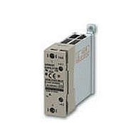
G3PA-220B-VD DC5-24
Description
SOLID STATE RELAY
Manufacturer
Omron
Series
G3PAr
Specifications of G3PA-220B-VD DC5-24
Circuit
SPST-NO (1 Form A)
Output Type
AC, Zero Cross
Load Current
20A
Voltage - Input
4 ~ 30VDC
Voltage - Load
19 ~ 264 V
Mounting Type
DIN Rail
Termination Style
Screw Terminal
Package / Case
SSR with Integrated Heatsink
Control Voltage Range
5 V to 24 V
Load Voltage Rating
200 V
Load Current Rating
20 A
Mounting Style
DIN Rail
Lead Free Status / RoHS Status
Lead free / RoHS Compliant
On-state Resistance
-
Lead Free Status / Rohs Status
Lead free / RoHS Compliant
Other names
G3PA-220B-VDDC5-24
G3PA220BVDDC524
G3PA220BVDDC524


Safety Precautions
■ Precautions for Correct Use
Please observe the following precautions to prevent failure to oper-
ate, malfunction, or undesirable effect on product performance.
Load Connection
For an AC load, use a power supply rated at 50 or 60 Hz.
The maximum operating frequency is 10 Hz.
The G3PA-(VD) has a built-in varistor for overvoltage protection.
At a low applied voltage, such as 24 VAC, the load current is not fully
supplied. When the Unit is switched ON, the voltage required to
power the Unit deprives the output signal of the necessary voltage
level and thus creates loss time. The lower the load voltage is, the
greater the loss time is. This condition, however, will not create any
serious problems.
Mounting
When attaching a heat sink to the G3PA-(VD), in order to facilitate heat dissipation, apply silicone grease or equivalent heat-conductive grease on
the heat sink. (Toshiba Silicone, Shinetsu Silicone, etc.)
Tighten the mounting screws of the heat sink with a torque of 0.78 to 0.98 N•m.
The rated ambient
temperature is
40°C. (30°C for
400 V.)
Note: Leave a distance of 60 mm min. between SSRs and ducts (especially above the SSR).
Loss time
Vertical mounting
Close mounting
Horizontal mounting
G3PA
G3PA
Panel
For a DC or L load, a diode should be connected in parallel the load
to absorb the counter electromotive force of the load.
Noise Terminal Voltage according to
EN55011
The G3PA-(VD) complies with EN55011 standards when a capacitor
is connected to the load power supply as shown in the following cir-
cuit diagram.
Recommended Capacitor: 1 μF, 250 VAC
DIN track
80 mm
DIN track
Panel
Input
• Screw or DIN track
• Vertical mounting should
• Close mounting is also
• Close mounting is possible for
• Leave a distance of 80 mm
• With vertical mounting,
mounting is possible.
usually be used.
possible.
up to 3 G3PA SSRs. (If there
are 4 or more SSRs, mount at
intervals of 10 mm min.)
Reduce the load current by
10% for G3PA-210B-VD,
-220B-VD, -240B-VD and by
20% for G3PA-260B-VD, -
420B-VD(-2), -430B-VD(-2),
-450B-VD-2.
reduce the load current by
30%. (Refer to the Load
Current vs. Ambient
Temperature graph.)
Input
Solid State Relays
SSR
G3PA-(VD)
Output
Load
Load
G3PA
Load power
supply
449
Related parts for G3PA-220B-VD DC5-24
Image
Part Number
Description
Manufacturer
Datasheet
Request
R

Part Number:
Description:
SOLID STATE RELAY
Manufacturer:
Omron
Datasheet:

Part Number:
Description:
G6S-2GLow Signal Relay
Manufacturer:
Omron Corporation
Datasheet:
Part Number:
Description:
Compact, Low-cost, SSR Switching 5 to 20 A
Manufacturer:
Omron Corporation
Datasheet:
Part Number:
Description:
Manufacturer:
Omron Corporation
Datasheet:
Part Number:
Description:
Manufacturer:
Omron Corporation
Datasheet:
Part Number:
Description:
Manufacturer:
Omron Corporation
Datasheet:
Part Number:
Description:
Manufacturer:
Omron Corporation
Datasheet:
Part Number:
Description:
Manufacturer:
Omron Corporation
Datasheet:
Part Number:
Description:
Manufacturer:
Omron Corporation
Datasheet: