G2RL-1A-CF DC24 Omron, G2RL-1A-CF DC24 Datasheet - Page 2
G2RL-1A-CF DC24
Manufacturer Part Number
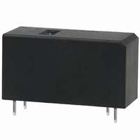
G2RL-1A-CF DC24
Description
POWER PCB RELAY
Manufacturer
Omron
Series
G2RLr
Specifications of G2RL-1A-CF DC24
Relay Type
General Purpose
Contact Form
SPST-NO (1 Form A)
Contact Rating (current)
12A
Switching Voltage
440VAC, 300VDC - Max
Coil Type
Standard
Coil Current
16.7mA
Coil Voltage
24VDC
Turn On Voltage (max)
16.8 VDC
Turn Off Voltage (min)
2.4 VDC
Mounting Type
Through Hole
Termination Style
PC Pin
Circuit
SPST-NO (1 Form A)
Contact Rating @ Voltage
12A @ 250VAC
Control On Voltage (max)
16.8 VDC
Control Off Voltage (min)
2.4 VDC
Current, Rating
12 A
Function
General Purpose
Number Of Pins
4
Power, Rating
3000⁄288 VA⁄W
Standards
UL, CSA, VDE
Termination
Through Hole
Voltage, Control
24 VDC
Voltage, Rating
440 VAC
Lead Free Status / RoHS Status
Lead free / RoHS Compliant
Lead Free Status / RoHS Status
Lead free / RoHS Compliant
Other names
G2RL-1A-CF-DC24
G2RL-1A-CF-DC24
G2RL1ACFDC24
Z2519
G2RL-1A-CF-DC24
G2RL1ACFDC24
Z2519


G2RL
Specifications
■
Note: The rated current and coil resistance are measured at a coil temperature of 23 ° C with a tolerance of ± 10%.
■
Note: 1. Values in parentheses are those for the high-capacity model.
■
Note: Values in the above table are the initial values.
■
UL508 (File No. E41643)
Rated voltage
Rated current
Coil resistance
Must operate voltage
Must release voltage
Max. voltage
Power consumption
Number of poles
Contact material
Load
Rated load
Rated carry current
Max. switching voltage
Max. switching current
Max. switching power
Contact resistance
Operate (set) time
Release (reset) time
Max. operating frequency
Insulation resistance
Dielectric strength
Impulse withstand voltage
Vibration resistance
Shock resistance
Endurance (Mechanical)
Ambient temperature
Ambient humidity
Weight
G2RL-1A
G2RL-1
G2RL-1A-E
G2RL-1-E
G2RL-2A
G2RL-2
Coil Ratings
Contact Ratings
Characteristics
Approved Standards
2. Contact your OMRON representative for the ratings on fully sealed models.
Model
Item
100 m Ω max.
15 ms max. (Approx. 7 ms typical)
5 ms max. (Approx. 2 ms typical)
Mechanical:18,000 operation/hr
Electrical:1,800 operation/hr at rated load
1,000 M Ω min. (at 500 VDC)
5,000 VAC, 1 min between coil and contacts
1,000 VAC, 1 min between contacts of same polar-
ity
10 kV (1.2 × 50 µ s) between coil and contact
Destruction: 10 to 55 to 10 Hz, 0.75 mm single amplitude (1.5 mm double amplitude)
Malfunction: 10 to 55 to 10 Hz, 0.75 mm single amplitude (1.5 mm double amplitude)
Destruction: 1,000 m/s
Malfunction: Energized:
20,000,000 operations (at 18,000 operations/hr)
Operating:
Storage:
5% to 85%
Approx. 12 g
SPST-NO
SPDT
SPDT (High capacity)
DPST-NO
DPDT
SPST-NO (High capacity)
Contact form
5 VDC
80.0 mA
62.5 Ω
70% max. of the rated voltage
10% min. of the rated voltage
180% of rated voltage (at 23 ° C)
Approx. 400 mW
1 pole
AgSnO
Resistive load (cos φ =1)
12 A (16 A) at 250 VAC
12 A (16 A) at 24 VDC
(See note 2.)
12 A (16 A)
(See note 2.)
440 VAC, 300 VDC
12 A (16 A)
3,000 VA (4,000 VA)
Not energized: 100 m/s
–40 ° C to 85 ° C (with no icing)
–40 ° C to 85 ° C (with no icing)
2
1 pole
2
100 m/s
12 VDC
33.3 mA
360 Ω
3 to 48 VDC
2
2
Coil ratings
5,000 VAC, 1 min between coil and contacts
2,500 VAC, 1 min between contacts of different
polarity
1,000 VAC, 1 min between contacts of same polar-
ity
24 VDC
16.7 mA
1,440 Ω
2 poles
AgNi
Resistive load (cos φ =1)
8 A at 250 VAC
8 A at 30 VDC
(See note 2.)
8 A (70 ° C)/5 A (85 ° C)
(See note 2.)
8 A
2,000 VA
12 A at 250 VAC (General use)
12 A at 24 VDC (Resistive)
16 A at 250 VAC (General use)
16 A at 24 VDC (Resistive)
8 A at 277 VAC (General use)
8 A at 30 VDC (Resistive)
2 poles
Contact ratings
48 VDC
8.96 mA
5,358 Ω
Approx. 430 mW
G2RL
225
Related parts for G2RL-1A-CF DC24
Image
Part Number
Description
Manufacturer
Datasheet
Request
R

Part Number:
Description:
POWER PCB RELAY
Manufacturer:
Omron
Datasheet:

Part Number:
Description:
POWER PCB RELAY
Manufacturer:
Omron
Datasheet:

Part Number:
Description:
POWER PCB RELAY
Manufacturer:
Omron
Datasheet:

Part Number:
Description:
POWER PCB RELAY
Manufacturer:
Omron
Datasheet:

Part Number:
Description:
POWER PCB RELAY
Manufacturer:
Omron
Datasheet:
Part Number:
Description:
POWER PCB RELAY
Manufacturer:
Omron
Datasheet:
Part Number:
Description:
POWER PCB RELAY
Manufacturer:
Omron
Datasheet:
Part Number:
Description:
POWER PCB RELAY
Manufacturer:
Omron
Datasheet:
Part Number:
Description:
POWER PCB RELAY
Manufacturer:
Omron
Datasheet:
Part Number:
Description:
POWER PCB RELAY
Manufacturer:
Omron
Datasheet:

Part Number:
Description:
RELAY PWR SPST 12A 5VDC PCB
Manufacturer:
Omron
Datasheet:
Part Number:
Description:
POWER PCB RELAY
Manufacturer:
Omron
Datasheet:
Part Number:
Description:
POWER PCB RELAY
Manufacturer:
Omron
Datasheet:

Part Number:
Description:
RELAY, PCB, SPST-NO, 12VDC, 16A
Manufacturer:
Omron
Datasheet: