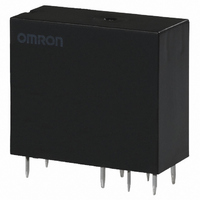
G2R-24-T130 DC24 Omron, G2R-24-T130 DC24 Datasheet - Page 4

G2R-24-T130 DC24
Manufacturer Part Number
G2R-24-T130 DC24
Description
RELAY
Manufacturer
Omron
Series
G2Rr
Datasheet
1.G2R-2-SND_DC24S.pdf
(19 pages)
Specifications of G2R-24-T130 DC24
Relay Type
General Purpose
Contact Form
DPDT (2 Form C)
Contact Rating (current)
5A
Switching Voltage
380VAC, 125VDC - Max
Coil Type
Standard
Coil Current
21.8mA
Coil Voltage
24VDC
Turn On Voltage (max)
16.8 VDC
Turn Off Voltage (min)
3.6 VDC
Mounting Type
Through Hole
Termination Style
PC Pin
Circuit
DPDT (2 Form C)
Contact Rating @ Voltage
5A @ 250VAC
Control On Voltage (max)
16.8 VDC
Control Off Voltage (min)
3.6 VDC
Contact Rating
5 A
Contact Termination
Quick Connect
Mounting Style
Plug-In
Power Consumption
530 mW
Contact Material
Silver Alloy
Coil Resistance
1.1 K Ohms
Lead Free Status / RoHS Status
Lead free / RoHS Compliant
Lead Free Status / RoHS Status
Lead free / RoHS Compliant
Other names
G2R-24-T130-DC24
G2R24T130DC24
G2R24T130DC24
G2R
Double-winding Latching Relays
Note:
I
PCB/Flux Protection, Plug-in, Quick-connect Terminal Relays
Note:
PCB/Flux Protection Relays
Note:
4
Rated voltage
Set coil
Reset coil
Must set voltage
Must reset voltage
Max. voltage
Power consumption
Number of poles
Load
Rated load
Rated carry current
Max. switching voltage 380 VAC, 125 VDC
Max. switching current 10 (1) A
Max. switching power
Failure rate
(reference value)
Number of poles
Load
Rated load
Rated carry current
Max. switching voltage 380 VAC, 125 VDC
Max. switching current 5 A
Max. switching power
Failure rate
(reference value)
Contact Ratings
1. The rated current and coil resistance are measured at a coil temperature of 23°C with a tolerance of ±10%.
2. Operating characteristics are measured at a coil temperature of 23°C.
1. P level:
2. ( ): Bifurcated crossbar contact type.
P level:
Item
Item
l
60
Rated current (see note 1.)
Coil resistance (see note 1.)
Coil inductance
(H) (ref. value)
Rated current
Coil resistance
Coil inductance
(H) (ref. value)
l
= 0.1 x 10
60
= 0.1 x 10
1 pole
Resistive load
(cos = 1)
10 (1) A at 250 VAC;
10 (1) A at 30 VDC
10 (1) A
2,500 (250) VA,
300 (30) W
100 mA at 5 VDC (1 mA at 5 VDC)
1 pole
Resistive load
(cos = 1)
5 A at 250 VAC;
5 A at 30 VDC
5 A
1,250 VA,
150 W
1 mA at 5 VDC
–6
/operation
–6
Bifurcated contacts
/operation
Armature OFF
Armature ON
Armature OFF
Armature ON
General-purpose, quick-connect terminal
Inductive load
(cos = 0.4;
L/R = 7 ms)
2 A at 250 VAC;
3 A at 30 VDC
500 VA,
90 W
Inductive load
(cos = 0.4;
L/R = 7 ms)
7.5 A at 250
VAC;
5 A at 30 VDC
1,875 VA,
150 W
5 VDC
167 mA
30
0.073
0.146
119 mA
42
0.003
0.006
70% max. of rated voltage
70% max. of rated voltage
140% of rated voltage (at 23 C)
Set coil: Approx. 850 mW; Reset coil: Approx. 600 mW
1 pole
Resistive load
(cos = 1)
5 A at 250 VAC;
5 A at 30 VDC
5 A
380 VAC, 125 VDC
5 A
1,250 VA,
150 W
100 mA at 5 VDC
2 poles
Resistive load
(cos = 1)
5 A at 250
VAC;
5 A at 30 VDC
5 A
380 VAC, 125 VDC
5 A
1,250 VA,
150 W
10 mA at 5 VDC
6 VDC
138 mA
43.5
0.104
0.208
100 mA
60
0.005
0.009
Inductive load
(cos = 0.4;
L/R = 7 ms)
2 A at 250 VAC;
3 A at 30 VDC
500 VA,
90 W
Inductive load
(cos = 0.4;
L/R = 7 ms)
2 A at 250 VAC;
3 A at 30 VDC
500 VA,
90 W
High-sensitivity
12 VDC
70.6 mA
170
0.42
0.83
50 mA
240
0.018
0.036
2 poles
Resistive load
(cos = 1)
3 A at 250 VAC;
3 A at 30 VDC
3 A
380 VAC, 125 VDC
3 A
750 VA,
90 W
10 mA at 5 VDC
1 pole
Resistive load
(cos = 1)
16 A at 250
VAC;
16 A at 30 VDC
16 A
380 VAC, 125 VDC
16 A
4,000 VA,
480 W
100 mA at 5 VDC
High-capacity
24 VDC
34.6 mA
694
1.74
3.43
25 mA
960
0.079
0.148
Inductive load
(cos = 0.4;
L/R = 7 ms)
1 A at 250 VAC;
1.5 A at 30 VDC
250 VA,
45 W
Inductive load
(cos = 0.4;
L/R = 7 ms)
8 A at 250 VAC;
8 A at 30 VDC
2,000 VA,
240 W
G2R


