EE-SX305 Omron, EE-SX305 Datasheet - Page 2
EE-SX305
Manufacturer Part Number
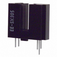
EE-SX305
Description
PHOTO MICROSENSOR
Manufacturer
Omron
Type
Transmissiver
Datasheet
1.EE-SX305.pdf
(4 pages)
Specifications of EE-SX305
Sensing Distance
0.134" (3.4mm)
Sensing Method
Transmissive
Output Configuration
NPN - Open Collector/Dark-ON
Mounting Type
Through Hole
Current - Supply
3.2mA
Voltage - Supply
4.5 V ~ 16 V
Package / Case
PCB Mount
Aperture Width
0.5 mm
Termination Style
Solder Pin
Number Of Elements
1
Output Device
PHOTO IC
Gap Width
3.4mm
Slit Width
0.5mm
Reverse Breakdown Voltage
4V
Collector-emitter Voltage
28V
Forward Current
15mA
Collector Current (dc) (max)
16mA
Power Dissipation
250mW
Pin Count
5
Mounting
Through Hole
Operating Temp Range
-40C to 75C
Operating Temperature Classification
Commercial
Lead Free Status / RoHS Status
Lead free / RoHS Compliant
Response Time
-
Lead Free Status / Rohs Status
Compliant
Other names
EE-SX305
EESX305
OR715
Z2201
Z2201
EESX305
OR715
Z2201
Z2201
Available stocks
Company
Part Number
Manufacturer
Quantity
Price
Company:

Part Number:
EE-SX305
Manufacturer:
OMRON
Quantity:
79
Part Number:
EE-SX305
Manufacturer:
OMRON/欧姆龙
Quantity:
20 000


■ Engineering Data
Note: The values in the parentheses apply to the EE-SX405.
182
Note: 1. Hysteresis denotes the difference in forward LED
LED Current vs. Ambient Temper-
ature Characteristics (Typical)
Forward Current vs. Collector
Dissipation Temperature Rating
Current Consumption vs. Supply
Voltage (Typical)
Ambient temperature Ta ( C)
Ambient temperature Ta ( C)
2. The value of the response frequency is measured
current value, expressed in percentage, calculated
from the respective forward LED currents when the
photo IC in turned from ON to OFF and when the
photo IC in turned from OFF to ON.
by rotating the disk as shown below.
I
FT
Supply voltage V
I
FT
OFF (I
Photomicrosensor (Transmissive)
0.5 mm
ON (I
FT
FT
ON)
OFF)
Ta = 25 C
I
F
= 0 mA (15 mA)
0.5 mm
V
R
CC
CC
L
= 330
= 5 V
2.1 mm
(V)
Forward Current vs. Forward
Voltage Characteristics (Typical)
Low-level Output Voltage vs.
Output Current (Typical)
Response Delay Time vs. Forward
Current (Typical)
EE-SX305/-SX405
Disk
V
R
Ta = 25 C
Forward voltage V
CC
L
Forward current I
Output current I
= 330
= 5 V
Ta = 30 C
Ta = 25 C
Ta = 70 C
V
(EE-SX3@@)
V
(EE-SX4@@)
3. The following illustrations show the definition of response
OUT
OUT
delay time. The value in the parentheses applies to the EE-
SX405.
Ta = 25 C
V
I
Output
F
CE
Input
= 0 mA (15 mA)
= 5 V
C
F
F
(mA)
(V)
(mA)
EE-SX305
LED Current vs. Supply Voltage
(Typical)
Repeat Sensing Position
Characteristics (Typical)
Low-level Output Voltage vs. Am-
bient Temperature Characteristics
(Typical)
Ambient temperature Ta ( C)
Output
I
Input
FT
I
OL
OFF (I
Supply voltage V
= 16 mA
I
Distance d (mm)
FT
I
OL
ON (I
FT
EE-SX405
= 5 mA
ON)
FT
Ta = 25 C
I
V
R
n = repeat 20 times
V
F
I
OFF)
CC
L
F
CC
= 15 mA
= 330
= 0 mA (15 mA)
= 5 V
= 5 V
Center of optical axis
Ta = 25 C
R
d
L
1
CC
= 0.01 mm
= 1 k
(V)
Related parts for EE-SX305
Image
Part Number
Description
Manufacturer
Datasheet
Request
R


Part Number:
Description:
PHOTO MICROSENSOR
Manufacturer:
Omron
Datasheet:

Part Number:
Description:
PHOTO MICROSENSOR :
Manufacturer:
Omron
Datasheet:

Part Number:
Description:
PHOTO MICROSENSOR
Manufacturer:
Omron
Datasheet:

Part Number:
Description:
PHOTO MICROSENSOR
Manufacturer:
Omron
Datasheet:

Part Number:
Description:
Detector Connector For EE-SPW
Manufacturer:
Omron
Datasheet:

Part Number:
Description:
PHOTO MICROSENSOR
Manufacturer:
Omron
Datasheet:

Part Number:
Description:
PHOTO MICROSENSOR
Manufacturer:
Omron
Datasheet:

Part Number:
Description:
5mm SLOT PMS L-ON NPN C MOUNT
Manufacturer:
Omron
Datasheet:
Part Number:
Description:
Emitter Connector
Manufacturer:
Omron
Datasheet:
Part Number:
Description:
PHOTO MICROSENSOR
Manufacturer:
Omron
Datasheet:
Part Number:
Description:
PHOTO MICROSENSOR
Manufacturer:
Omron
Datasheet:
Part Number:
Description:
PHOTO MICROSENSOR
Manufacturer:
Omron
Datasheet: