A7BS-206-1 Omron, A7BS-206-1 Datasheet - Page 3
A7BS-206-1
Manufacturer Part Number
A7BS-206-1
Description
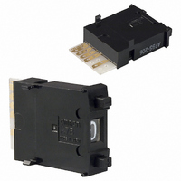
Thumbwheel Switch,BCD,BINARY CODED,Number Of Positions:7,SOLDER Terminal,PUSHBUTTON
Manufacturer
Omron
Series
A7BSr
Specifications of A7BS-206-1
Output Code
BCD
Read Out
0 ~ 9
Actuator Type
Pushwheel
Mounting Type
Panel Mount, Snap-In (Front)
Termination Style
Card Edge
Component Mounting Area
No
Actuator
Thumbwheel
Number Of Sections
1
Contact Rating
1 Amp
Switch Terminals
Solder
No. Of Switch Positions
6
Contact Current Max
1A
Panel Cutout Height
22.4mm
Switch Features
Push Actuator
Overall Height
24mm
Color
Black
Operation
Binary Coded Decimal
Panel Cutout Width
54.8mm
Rohs Compliant
Yes
Lead Free Status / RoHS Status
Lead free / RoHS Compliant
Lead Free Status / RoHS Status
Lead free / RoHS Compliant
Other names
A7BS2061
SW266
SW266


Dimensions
Switches
A7BS-2@@(-1)
Solder Terminals
Thumbwheel Switches with External Stoppers:
A7BS-20@-S(-1)
Refer to page 7 for details.
A7BL-206(-1)
A7BL-207(-1)
Solder Terminals,
Locking Models
• Use A7BS-S Stopper Pins to make dial display restrictions for these Switches.
• Insert the Stopper Pins in the positions required to give the desired display range. For
example, for a display range of 0 to 5, insert a Stopper Pin at position 1 (see following
diagram) to stop the display from going above 5 when the (+) button is pressed, and insert
a Stopper Pin at position 2 to stop the display from going below 0 when the (-) button is
pressed.
22
20.6
24
* If the output code is 06, the dimension is 32.5;
if the output code is 07, the dimension is 43.5.
24
3
3
Ten, 1.2 dia.
8
6.9
± 0.1
7
8
6.9
*
8
6
± 0.1
24.5
0.8
9
5
A
B
3.6
0.8
P=8
B
A
3.8
0
4
P=8
± 0.2
1
3
2
± 0.2
2.8
5.5
* If the output code is 06, the dimension is 32.5;
16
if the output code is 07, the dimension is 43.5.
* If the output code is 06 or 54, the dimension is 32.5;
if the output code is 07 or 55, the dimension is 43.5.
When setting
15.4
2.6
16
24
2
6.1
2.8
2.6
5.5
2.8
Panel Cutout
C +
Pin insertion position (1)
7
0.3
0
8
6
Panel Cutout
Panel thickness: 1 to 3
24.5
9
5
C
Panel thickness: 1 to 3
24.5
+ 0.3
*
0
0
4
Pin insertion position (2)
*
1
3
Solder terminal
2
22.4
Solder terminal
+0.4
0
22.4
20.6
20.6
+ 0.4
0
22
22
Note: 1. The dimensions above include both End
Stopper Pins
Note: 1. Two pins constitute one set.
Note: 1. The dimensions above include both End
Number of
Number of
Switches
Switches
10
(n)
10
(n)
1
2
3
4
5
6
7
8
9
1
2
3
4
5
6
7
8
9
2. Unless otherwise specified, a tolerance of
2. The first shipment is free and is attached
2. Unless otherwise specified, a tolerance of
Caps, and will increase 8 mm for each
Spacer inserted.
±0.4 mm applies to all dimensions.
The tolerance for multiple connection is
±(number of units x 0.4) mm.
to the Switch.
Order the A7BS-S separately if it is
required for maintenance.
Caps, and will increase 8 mm for each
Spacer inserted.
±0.4 mm applies to all dimensions.
The tolerance for multiple connection is
±(number of units x 0.4) mm.
2.4 dia.
(n x 8 + 8)
(n x 8 + 8)
Size A
Size A
16
24
32
40
48
56
64
72
80
88
16
24
32
40
48
56
64
72
80
88
0.4
A7BS/A7BL
(n x 8 + 6)
2.7
(n x 8 + 6)
Size B
Size B
14
22
30
38
46
54
62
70
78
86
14
22
30
38
46
54
62
70
78
86
1.2 dia.
(Unit: mm)
Size C
Size C
14.4
22.4
30.4
38.4
46.8
54.8
62.8
70.8
78.8
86.8
14.4
22.4
30.4
38.4
46.8
54.8
62.8
70.8
78.8
86.8
3
Related parts for A7BS-206-1
Image
Part Number
Description
Manufacturer
Datasheet
Request
R

Part Number:
Description:
Thumbwheel Switch,BCD,BINARY CODED,Number Of Positions:7,SOLDER Terminal,PUSHBUTTON
Manufacturer:
Omron
Datasheet:

Part Number:
Description:
Thumbwheel Switch,BCD,BINARY CODED,Number Of Positions:8,SOLDER Terminal,PUSHBUTTON
Manufacturer:
Omron
Datasheet:

Part Number:
Description:
Thumbwheel Switch,BCD,BINARY CODED,Number Of Positions:8,SOLDER Terminal,PUSHBUTTON
Manufacturer:
Omron
Datasheet:
Part Number:
Description:
THUMBWHEEL W/RED CHAR
Manufacturer:
Omron
Datasheet:
Part Number:
Description:
Thumbwheel Switch,BCD,BINARY CODED,Number Of Positions:7,SOLDER Terminal,PUSHBUTTON
Manufacturer:
Omron
Datasheet:
Part Number:
Description:
Thumbwheel Switch,BCD,BINARY CODED,Number Of Positions:8,SOLDER Terminal,PUSHBUTTON
Manufacturer:
Omron
Datasheet:
Part Number:
Description:
Thumbwheel Switch,BCD,BINARY CODED,Number Of Positions:8,SOLDER Terminal,PUSHBUTTON
Manufacturer:
Omron
Datasheet:
Part Number:
Description:
PUSHWHEEL SWITCH +/-
Manufacturer:
Omron
Datasheet:

Part Number:
Description:
PUSHWHEEL SWITCH
Manufacturer:
Omron
Datasheet:
Part Number:
Description:
THUMBWHEEL SWITCH
Manufacturer:
Omron
Datasheet:

Part Number:
Description:
THUMBWHEEL SWITCH
Manufacturer:
Omron
Datasheet:
Part Number:
Description:
THUMBWHEEL
Manufacturer:
Omron
Datasheet: