A7B-C Omron, A7B-C Datasheet
A7B-C
Specifications of A7B-C
SW270


Related parts for A7B-C


A7B-C Summary of contents
Page 1
... A7DP-206-1 A7D-206 --- A7D-206-1 A7D-106 --- A7D-106-1 --- --- A7CN-106-1 A7CN-206 --- A7CN-206-1 A7CN-L206 --- A7CN-L206-1 A7BL-206 A7BL-207 A7BL-206-1 A7BL-207-1 A7BS-206 A7BS-207 A7BS-206-1 A7BS-207-1 A7j (decimal (binary (binary code with coded coded component hexadecimal) hexadecimal adding with provision) component adding provision) --- --- --- --- --- --- --- --- --- --- --- --- --- --- --- --- --- --- --- --- --- (A7BS-219) A7BS-254 A7BS-255 (A7BS-219-1) A7BS-254-1 A7BS-255-1 ...
Page 2
... A7CN-1Pj-1 A7CN-2Pj A7CN-2Pj-1 A7B-PA A7B-PA-1 A7P-PA A7P-PA-1 A7P-PA A7P-PA-1 A7j (decimal (binary (binary code with coded coded component hexadecimal) hexadecimal adding with provision) component adding provision) --- --- --- A7PS-219 A7PS-254 A7PS-255 A7PS-219-1 A7PS-254-1 A7PS-255-1 A7PH-219 --- --- A7PH-219-1 Connectors Solder terminals PCB terminals --- --- --- --- --- --- --- --- A7B-C A7B-CP --- --- --- --- 13 ...
Page 3
... A7j Thumbwheel Switches Models and Terminals Color mounting ti A7MD/ PCB Black A7MD-jj-D terminal (see note 1) (see note 1) Fastens to panel via printed circuit board. A7MA-1 Solder Black Screw mounting g terminal PCB terminal A7MA-2 Solder Light Snap-in p terminal gray Black PCB Light terminal ...
Page 4
... A7PS, A7PH, A7SS, and A7AS the outside of the A7BS-j Stopper Pin with which the user can make any setting The A7CN-2, A7CN-1, A7CN-L, A7MD, and A7MA cannot be equipped with Stoppers SEC Product name Model Number of Units A7BS-206-1 2 A7B-PA-1 1 A7B-M-1 1 set A7B-CP 2 A7j 15 ...
Page 5
... Storage: –20°C to 80°C Ambient humidity Operating: 45% to 85% Max. operating force 3.45 N (350 gf) 16 A7CN/A7CN-L A7BL/A7BS /A7D-2 /A7BS-20j VDC 0 max. 10 MΩ min. (at 500 VDC) 1,000 MΩ min. (at 500 VDC) 200 VAC, 600 VAC, 50/60 Hz for 1 min 50/60 Hz for 1 min 2 2 min ...
Page 6
... A7j Thumbwheel Switches Item A7MD/A7MD-jj-D Switching capacity (resistive VDC load 0.1 A Continuous carry current 1 A max. 200 mΩ max., 10 Ω Contact resistance max. (see note 2) Insulation Between 10 MΩ min. (at 500 VDC) resistance non-connected (see note 1) terminals Between 1,000 MΩ min. (at 500 VDC) ...
Page 7
... A7j When a Switch is inserted into a Connector, e.g., for the A7BS, the common terminal C becomes connector terminal 2, and terminals 1 and 2 become connector terminals 4 and 5, respectively. 06: Binary-coded Decimal Output, Single-sided Board Thumbwheel Switch Unit Terminal numbers Output Code Types Decimal Code 03: Decimal Code Output ...
Page 8
... A7j Example of A7BS-206-PM Model Switch Unit or Common Connector terminal number A7BS Switch Unit C Connector 2 Dial + (0) – (1) + (2) – (3) + (4) – (5) + (6) – (7) + (8) – (9) Note: 1. The solid dot S indicates that the internal switch is ON. 2. Numbers enclosed in parentheses are the dial displays for the A7BS-206 ...
Page 9
... A7MA (see Switch Unit C note) A7SS A7SS A7AS Connector 1, 3 A7PS A7PH Dial Note: There is no Connector on the A7MA. 20 Binary-coded Hexadecimal 54: Binary-coded Hexadecimal Output Terminals connected Model Switch Unit or to common A7BS A7BS Switch Unit Connector A7PS Switch Unit Connector Dial ...
Page 10
... A7j Dimensions Note: All units are in millimeters unless otherwise indicated. Push-operated Switches A7DP-206(-1) PCB Terminals, Pen-push Model Panel Cutout Note: Common terminal the bottom when the Switch Unit is viewed from the front. A7D-106(-1) PCB Terminals Panel Cutout Note: Common terminal the bottom when the Switch Unit is viewed from the front ...
Page 11
... Panel thickness Note: 1. The dimensions above include both End Caps, and will increase 5.08 mm for each Spacer inserted. 2. Unless otherwise specified, a tolerance of ±0.4 mm ap- plies to all dimensions. The tolerance for multiple connection is ±(number of units x 0.4) mm. Number of Switches ( Note: 1. The dimensions above include both End Caps, and will PCB terminal increase 6 mm for each Spacer inserted ...
Page 12
... PCB terminal Panel thickness Note: 1. The dimensions above include both End Caps, and will increase 6 mm for each Spacer inserted. 2. Unless otherwise specified, a tolerance of ±0.4 mm ap- plies to all dimensions. The tolerance for multiple connection is ±(number of units x 0.4) mm. Number of Switches ( PCB terminal ...
Page 13
... Locking Models When setting Panel Cutout Note: If the output code is 06, the dimension is 32.5; if the output code is 07, the dimension is 43.5. A7BS-2jj(-1) A7BS-20jj(-1) Solder Terminals Panel Cutout Note: If the output code 54, the dimension is 32.5; if the output code 55, the dimension is 43.5. 24 Number of ...
Page 14
... Note: 1. The dimensions above include both End Caps, and will increase 10 mm for each Spacer inserted. Panel thickness Unless otherwise specified, a tolerance of ±0.4 mm ap- plies to all dimensions. The tolerance for multiple connection is ±(number of units x 0.4) mm. Number of Switches ( 2. Note: 1. The dimensions above include both End Caps, and will increase 6 mm for each Spacer inserted. 2. Unless otherwise specified, a tolerance of ± ...
Page 15
... Note: If the output code is 06, the dimension is 19; if the output code is 07, the dimension is 31. A7MA-1jj-P2 PCB Terminals (See note) Panel thickness: 2 Two, M2.6 Note: If the output code is 06, the dimension is 19; if the output code is 07, the dimension is 31. 26 Number of Switches ( (See note ...
Page 16
... Panel thickness Note: 1. The dimensions above include both End Caps, and will increase 6 mm for each Spacer inserted. Panel Cutout 2. Unless otherwise specified, a tolerance of ±0.4 mm ap- plies to all dimensions. The tolerance for multiple connection is ±(number of units x 0.4) mm. Number of Switches ( 2. Note: 1 ...
Page 17
... Panel thickness: 3.4 increase 12.7 mm for each additional Switch inserted (6.35-mm wide Spacers are also available). 2. Unless otherwise specified, a tolerance of ±0.4 mm ap- plies to all dimensions. The tolerance for multiple connection is ±(number of Four 3.2 holes units x 0.4) mm. Number of Switches ( (See note ...
Page 18
... End Caps for Push-operated Switches A7D-1M(-1) Screw Mounting (Back Mounting) Left Side Right Side A7CN-1M-1 Screw Mounting Left Side Right Side A7B-M(-1) Snap-in Panel Mounting Left Side Right Side A7D-2M(-1) Snap-in Mounting (Front Mounting) Left Side A7CN-2M-1 Snap-in Mounting Left Side ...
Page 19
... A7AS-M(-1) Snap-in Panel Mounting Left Side Right Side Spacers for Push-operated Switches A7D-1PA(-1) Screw Mounting (Back Mounting) A7CN-1P-1 Screw Panel Mounting Model A7B-PA(-1) Snap-in Panel Mounting 30 A7M-1M Screw Panel Mounting Left Side Right Side A7SS-M and SRT-M Screw Panel Mounting Left Side ...
Page 20
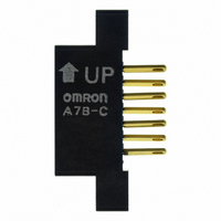
... P = 2.54 Inserting Connectors Insert Connectors with the “UP” arrow pointing up. Connector Note: Unless otherwise indicated, dimensional tolerances for dimensions in the models above are "0.4 mm. A7M-1PA Screw Panel Mounting A7B-CP PCB Terminals 0 2.54 A7j °C S PCS SEC 31 ...
Page 21
... A7CN-2/A7CN-1 A7BL /A7CN-L (solder terminals) (PCB terminals) -- 14, 1-dia. holes 28, 1-dia. holes -- -- -- A7j A7BS/A7BS-20j-S A7PS/A7PH (solder terminals) (solder terminals) -- 22, 1-dia. holes 10, 1-dia. 14, 1-dia. holes holes 23, 1-dia. holes 28, 1-dia. holes -- 44, 1-dia. holes 10, 1-dia. 14, 1-dia. holes holes 23, 1-dia. holes 28, 1-dia. holes ...
Page 22
... A7j Thumbwheel Switches Output A7MD code (PCB terminals (13) 07 (36 A7MA-j A7MA-j-P2 (solder terminals) (PCB terminals 10, 1-dia. holes 10, 1-dia. holes 18, 1-dia. holes 18, 1-dia. holes -- -- -- -- -- -- -- -- A7j A7SS/A7AS (solder terminals) -- 22, 1-dia. holes 22, 1-dia. holes 44, 1-dia. holes -- -- 44, 1-dia. holes -- 33 ...
Page 23
... Diode diodes Thumbwheel Switch Note: Use For mounting resistors Thumbwheel Switch 34 Circuit board For Programmable Controller inputs (OMRON C500 or C2000H) Diode Thumbwheel Switch (e.g., A7PS-207) the terminal marked with the as- terisk * if the common terminal needs no re- sistor or diode. Resistor As a voltage divider or digital variable resistor Thumbwheel Switch (e ...
Page 24
... Connectors Insert Connectors while keeping the arrow pointing up (refer to page 31). Connector insertion load is about 1.5 kg for each A7B-C. Setting the Stopper (A7BS-20j-S) With the A7BS-20j-S, any range can be set outside with the Stop- per Pin. Insert the Stopper Pin using the following procedure: ...
Page 25
... Confirm that the (–) push-button can no longer be pushed after reaching the lower limit of (“0”). This completes the setting. For Stoppers other than those for the A7BS-20-S, refer to pages the Selection Guide as well as the ordering information on page 15. All manufactured Switches have their ranges factory-set before shipment ...