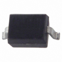
1N4448HWS-7-F Diodes Inc, 1N4448HWS-7-F Datasheet - Page 2

1N4448HWS-7-F
Manufacturer Part Number
1N4448HWS-7-F
Description
DIODE SWITCH 80V 200MW SOD-323
Manufacturer
Diodes Inc
Datasheet
1.1N4448HWS-7-F.pdf
(4 pages)
Specifications of 1N4448HWS-7-F
Voltage - Forward (vf) (max) @ If
1.25V @ 150mA
Voltage - Dc Reverse (vr) (max)
80V
Current - Average Rectified (io)
250mA
Current - Reverse Leakage @ Vr
100nA @ 80V
Diode Type
Standard
Speed
Fast Recovery =< 500ns, > 200mA (Io)
Reverse Recovery Time (trr)
4ns
Capacitance @ Vr, F
3.5pF @ 0V, 1MHz
Mounting Type
Surface Mount
Package / Case
SOD-323
Product
Switching Diodes
Peak Reverse Voltage
80 V
Forward Continuous Current
0.25 A
Max Surge Current
4 A
Configuration
Single
Recovery Time
4 ns
Forward Voltage Drop
1.25 V
Maximum Reverse Leakage Current
0.1 uA
Operating Temperature Range
- 65 C to + 150 C
Maximum Operating Temperature
+ 150 C
Minimum Operating Temperature
- 65 C
Mounting Style
SMD/SMT
Lead Free Status / RoHS Status
Lead free / RoHS Compliant
Other names
1N4448HWS-FDITR
Available stocks
Company
Part Number
Manufacturer
Quantity
Price
Part Number:
1N4448HWS-7-F
Manufacturer:
DIODES/美台
Quantity:
20 000
Thermal Characteristics
Electrical Characteristics
Maximum Ratings
Non-Repetitive Peak Reverse Voltage
Peak Repetitive Reverse Voltage
Working Peak Reverse Voltage
DC Blocking Voltage
RMS Reverse Voltage
Forward Continuous Current
Average Rectified Output Current
Non-Repetitive Peak Forward Surge Current
Power Dissipation (Note 4)
Thermal Resistance Junction to Ambient Air (Note 4)
Operating and Storage Temperature Range
Reverse Breakdown Voltage (Note 5)
Forward Voltage
Peak Reverse Current (Note 5)
Total Capacitance
Reverse Recovery Time
Notes:
1N4448HWS
Document number: DS30196 Rev. 10 - 2
300
200
100
4. Part mounted on FR-4 PC board with recommended pad layout, which can be found on our website at http://www.diodes.com.
5. Short duration pulse test used to minimize self-heating effect.
0
0
25
T , AMBIENT TEMPERATURE ( C)
A
Note 4
Fig. 1 Power Derating Curve
Characteristic
Characteristic
Characteristic
@T
50
A
= 25°C unless otherwise specified
75
@T
A
= 25°C unless otherwise specified
125
@ t = 1.0μs
@ t = 1.0s
°
150
175
www.diodes.com
Symbol
V
2 of 4
V
BR(R)
I
C
RM
t
FM
rr
T
T
Symbol
Symbol
V
J
V
V
R(RMS)
R
V
I
, T
I
RWM
V
FSM
P
RRM
FM
I
RM
θ JA
O
R
D
STG
0.62
Min
100
80
⎯
⎯
⎯
⎯
⎯
⎯
10
0.1
1
0
V , INSTANTANEOUS FORWARD VOLTAGE (mV)
F
0.855
Max
0.72
1.25
100
1.0
3.5
4.0
⎯
50
30
25
Fig. 2 Typical Forward Characteristics
200
-65 to +150
Value
Value
Unit
100
500
250
200
625
4.0
1.0
nA
μA
μA
nA
pF
400
80
57
ns
V
V
T = 25 C
A
I
I
I
I
I
V
V
V
V
V
I
I
R
F
F
F
F
F
rr
°
R
R
R
R
R
= 0.1 x I
= 5.0mA
= 10mA
= 100mA
= 150mA
= I
= 100μA
600
= 80V
= 75V, T
= 25V, T
= 20V
= 0, f = 1.0MHz
R
= 10mA,
Test Condition
R
1N4448HWS
, R
J
J
800
= 150°C
= 150°C
L
= 100Ω
© Diodes Incorporated
°C/W
November 2010
Unit
Unit
mW
mA
mA
°C
V
V
V
A
1,000


