BAS19-7-F Diodes Inc, BAS19-7-F Datasheet

DIODE SWITCH 100V 250MW SOT23-3

BAS19-7-F

Manufacturer Part Number
BAS19-7-F
Description
DIODE SWITCH 100V 250MW SOT23-3
Manufacturer
Diodes Inc
Datasheet

Specifications of BAS19-7-F

Voltage - Forward (vf) (max) @ If
1.25V @ 200mA
Voltage - Dc Reverse (vr) (max)
100V
Current - Average Rectified (io)
200mA
Current - Reverse Leakage @ Vr
100nA @ 100V
Diode Type
Standard
Speed
Small Signal =< 200mA (Io), Any Speed
Reverse Recovery Time (trr)
50ns
Capacitance @ Vr, F
5pF @ 0V, 1MHz
Mounting Type
Surface Mount
Package / Case
SOT-23-3, TO-236-3, Micro3™, SSD3, SST3
Product
Switching Diodes
Peak Reverse Voltage
120 V
Forward Continuous Current
0.4 A
Max Surge Current
2.5 A
Configuration
Single
Recovery Time
50 ns
Forward Voltage Drop
1.25 V
Maximum Reverse Leakage Current
0.1 uA
Operating Temperature Range
- 65 C to + 150 C
Maximum Operating Temperature
+ 150 C
Minimum Operating Temperature
- 65 C
Mounting Style
SMD/SMT
Lead Free Status / RoHS Status
Lead free / RoHS Compliant
Other names
BAS19-FDITR

Available stocks

Company
Part Number
Manufacturer
Quantity
Price
Part Number:
BAS19-7-F
Manufacturer:
Diodes Inc
Quantity:
36 100
Thermal Characteristics
Electrical Characteristics
Maximum Ratings
Repetitive Peak Reverse Voltage
Working Peak Reverse Voltage
DC Blocking Voltage
RMS Reverse Voltage
Forward Continuous Current (Note 1)
Average Rectified Output Current (Note 1)
Non-Repetitive Peak Forward Surge Current
Repetitive Peak Forward Surge Current (Note 1)
Power Dissipation (Note 1)
Thermal Resistance Junction to Ambient Air (Note 1)
Operating and Storage Temperature Range
Reverse Breakdown Voltage (Note 2)
Forward Voltage
Reverse Current @ Rated DC Blocking Voltage (Note 2)
Total Capacitance
Reverse Recovery Time
Features
Notes:
BAS19 / BAS20 / BAS21
Document number: DS12004 Rev. 20 - 2
Fast Switching Speed
Surface Mount Package Ideally Suited for Automated Insertion
For General Purpose Switching Applications
High Conductance
Lead, Halogen and Antimony Free, RoHS Compliant
“Green” Device (Notes 3 and 4)
Qualified to AEC-Q101 Standards for High Reliability
1. Part mounted on FR-4 board with recommended pad layout, which can be found on our website at http://www.diodes.com/datasheets/ap02001.pdf.
2. Short duration pulse test used to minimize self-heating effect.
3. No purposefully added lead. Halogen and Antimony Free.
4. Product manufactured with Data Code V9 (week 33, 2008) and newer are built with Green Molding Compound. Product manufactured prior to Date Code
V9 are built with Non-Green Molding Compound and may contain Halogens or Sb
Characteristic
Characteristic
Characteristic
@T
A
= 25°C unless otherwise specified
@T
A
= 25°C unless otherwise specified
TOP VIEW
@ t = 1.0μs
@ t = 1.0s
BAS19
BAS20
BAS21
www.diodes.com
SOT-23
Symbol
Symbol
V
1 of 3
V
V
V
R(RMS)
I
I
I
FSM
FRM
(BR)R
RWM
V
C
RRM
V
FM
I
I
t
O
R
rr
R
F
T
Mechanical Data
T
Symbol
J
R
, T
Please click here to visit our online spice models database.
P
θ JA
D
Case: SOT-23
Case Material: Molded Plastic. UL Flammability Classification
Rating 94V-0
Moisture Sensitivity: Level 1 per J-STD-020D
Terminals: Solderable per MIL-STD-202, Method 208
Lead Free Plating (Matte Tin Finish annealed over Alloy 42
leadframe).
Polarity: See Diagram
BAS19 Marking: KA8, KT3; KT2 - See Page 2
BAS20 Marking: KT2, KT3 - See Page 2
BAS21 Marking: KT3 - See Page 2
Ordering Information: See Page 2
Weight: 0.008 grams (approximate)
STG
2
O
Min
120
200
250
BAS19
Internal Schematic
3
SURFACE MOUNT FAST SWITCHING DIODE
Fire Retardants.
120
100
71
TOP VIEW
Max
1.25
100
1.0
5.0
15
50
-65 to +150
Value
BAS20
250
500
BAS19 / BAS20 / BAS21
200
150
106
400
200
625
2.5
0.5
Unit
nA
μA
pF
ns
V
V
I
I
I
T
T
V
I
I
R
F
F
F
rr
J
J
R
BAS21
= 100mA
= 200mA
= I
= 0.1 x I
= 100μA
= 25°C
= 100°C
= 0, f = 1.0MHz
250
200
141
Test Condition
R
= 30mA,
© Diodes Incorporated
°C/W
Unit
mW
R
°C
, R
L
June 2008
= 100Ω
Unit
mA
mA
mA
V
V
V
A

Related parts for BAS19-7-F

BAS19-7-F Summary of contents

Page 1

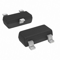
... Lead Free Plating (Matte Tin Finish annealed over Alloy 42 leadframe). • Polarity: See Diagram • BAS19 Marking: KA8, KT3; KT2 - See Page 2 • BAS20 Marking: KT2, KT3 - See Page 2 • BAS21 Marking: KT3 - See Page 2 • Ordering Information: See Page 2 • ...

Page 2

... V , INSTANTANEOUS REVERSE VOLTAGE (V) R Fig. 3 Typical Reverse Characteristics Ordering Information (Note 5) Part Number BAS19-7-F BAS20-7-F BAS21-7-F Notes: 5. For packaging details our website at http://www.diodes.com/datasheets/ap02007.pdf. Marking Information Date Code Key Year 2000 2001 2002 Code ...

Page 3

... Diodes Incorporated products are not authorized for use as critical components in life support devices or systems without the expressed written approval of the President of Diodes Incorporated. BAS19 / BAS20 / BAS21 Document number: DS12004 Rev Dimensions Value (in mm IMPORTANT NOTICE LIFE SUPPORT www.diodes.com BAS19 / BAS20 / BAS21 SOT-23 Dim Min Max A 0.37 0.51 B 1.20 1.40 C 2.30 2 ...

Related keywords