20CJQ060TR Vishay, 20CJQ060TR Datasheet

DIODE SCHOTTKY 60V 1A SOT-223

20CJQ060TR

Manufacturer Part Number
20CJQ060TR
Description
DIODE SCHOTTKY 60V 1A SOT-223
Manufacturer
Vishay
Datasheet

Specifications of 20CJQ060TR

Voltage - Forward (vf) (max) @ If
590mV @ 1A
Current - Reverse Leakage @ Vr
100µA @ 60V
Current - Average Rectified (io) (per Diode)
1A
Voltage - Dc Reverse (vr) (max)
60V
Diode Type
Schottky
Speed
Fast Recovery =< 500ns, > 200mA (Io)
Diode Configuration
1 Pair Common Cathode
Mounting Type
Surface Mount
Package / Case
SOT-223 (3 leads + Tab), SC-73, TO-261
Product
Schottky Rectifiers
Peak Reverse Voltage
60 V
Forward Continuous Current
4 A
Max Surge Current
385 A
Configuration
Dual Common Cathode
Forward Voltage Drop
0.75 V at 2 A
Maximum Reverse Leakage Current
100 uA
Operating Temperature Range
- 55 C to + 150 C
Mounting Style
SMD/SMT
Lead Free Status / RoHS Status
Contains lead / RoHS non-compliant
Reverse Recovery Time (trr)
-
Lead Free Status / RoHS Status
Contains lead / RoHS non-compliant, Lead free / RoHS Compliant
Other names
VS-20CJQ060TR
VS-20CJQ060TR
VS20CJQ060TR
VS20CJQ060TR

Available stocks

Company
Part Number
Manufacturer
Quantity
Price
Part Number:
20CJQ060TRPBF
Manufacturer:
IR
Quantity:
46 000
Document Number: 93273
Revision: 22-Aug-08
PRODUCT SUMMARY
MAJOR RATINGS AND CHARACTERISTICS
SYMBOL
I
V
I
V
T
VOLTAGE RATINGS
PARAMETER
DC reverse voltage
Working peak reverse voltage
ABSOLUTE MAXIMUM RATINGS
PARAMETER
Maximum average
forward current
See fig. 5
Maximum peak one cycle
non-repetitive surge current per leg
See fig. 7
Non-repetitive avalanche energy per leg
Repetitive avalanche current per leg
F(AV)
FSM
RRM
F
J
SOT-223
I
F(AV)
V
R
per device
Rectangular waveform
t
1 Apk, T
Range
Anode
p
= 5 µs sine
per leg
1
J
For technical questions, contact: diodes-tech@vishay.com
Common
common
cathode
Schottky Rectifier, 2 x 1 A
CHARACTERISTICS
= 125 °C (per leg)
Base
SYMBOL
2 x 1 A
2
4
I
I
60 V
F(AV)
E
FSM
I
AR
AS
3
Anode
SYMBOL
50 % duty cycle at T
5 µs sine or 3 µs rect. pulse
10 ms sine or 6 ms rect. pulse
T
Current decaying linearly to zero in 1 µs
Frequency limited by T
V
J
V
RWM
= 25 °C, I
R
AS
= 1 A, L = 3 mH
FEATURES
• Small foot print, surface mountable
• Low profile
• Very low forward voltage drop
• High frequency operation
• Guard ring for enhanced ruggedness and long term
• Common cathode
• Designed and qualified for industrial level
DESCRIPTION
The 20CJQ060 surface mount Schottky rectifier series has
been designed for applications requiring very low forward
drop and very small foot prints. Typical applications are in
portables, switching power supplies, converters, automotive
system, freewheeling diodes, battery charging, and reverse
battery protection.
TEST CONDITIONS
reliability
C
C
= 127 °C, rectangular waveform
= 109 °C, rectangular waveform
J
maximum V
20CJQ060
- 55 to 150
Following any rated load
condition and with rated
V
Vishay High Power Products
VALUES
RRM
A
0.56
385
= 1.5 x V
60
60
2
applied
R
typical
VALUES
20CJQ060
385
1.5
1.0
22
1
2
www.vishay.com
UNITS
UNITS
°C
A
V
A
V
V
UNITS
mJ
A
A
1

Related parts for 20CJQ060TR

20CJQ060TR Summary of contents

Page 1

... I FSM 10 ms sine rect. pulse ° Current decaying linearly to zero in 1 µ Frequency limited by T maximum V J For technical questions, contact: diodes-tech@vishay.com 20CJQ060 Vishay High Power Products VALUES UNITS 385 A 0. 150 °C 20CJQ060 UNITS ...

Page 2

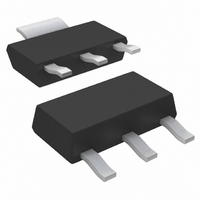
... MHz) 25 ° Measured lead to lead 5 mm from package body S dV/dt Rated V R SYMBOL TEST CONDITIONS ( Stg R thJL DC operation R thJA Case style SOT-223 For technical questions, contact: diodes-tech@vishay.com VALUES 0. °C J 0.75 0. 125 °C J 0.67 0 Rated 5 000 VALUES - 55 to 150 ...

Page 3

... Fig Maximum Thermal Impedance Z Document Number: 93273 Revision: 22-Aug-08 Schottky Rectifier Fig Typical Junction Capacitance vs. Reverse Voltage thJC For technical questions, contact: diodes-tech@vishay.com 20CJQ060 Vishay High Power Products Fig Typical Values of Reverse Current vs. Reverse Voltage (Per Leg) (Per Leg) Characteristics (Per Leg) www ...

Page 4

... Fig Maximum Non-Repetitive Surge Current (Per Leg) L High-speed IRFP460 Freewheel = 25 Ω diode 40HFL40S02 Fig Unclamped Inductive Test Circuit ; thJC at (I /D) (see fig. 6); F(AV D rated For technical questions, contact: diodes-tech@vishay.com Fig Forward Power Loss Characteristics (Per Leg) switch Document Number: 93273 Revision: 22-Aug-08 ...

Page 5

... Circuit configuration Common cathode - Package SOT-223 - Schottky “Q” series - Voltage rating (060 = None = Standard production PbF = Lead (Pb)-free LINKS TO RELATED DOCUMENTS For technical questions, contact: diodes-tech@vishay.com 20CJQ060 Vishay High Power Products 060 - 6 7 http://www.vishay.com/doc?95022 http://www.vishay.com/doc?95031 http://www.vishay.com/doc?95035 www.vishay.com 5 ...

Page 6

... Vishay disclaims any and all liability arising out of the use or application of any product described herein or of any information provided herein to the maximum extent permitted by law. The product specifications do not expand or otherwise modify Vishay’ ...

Related keywords