82CNQ030A Vishay, 82CNQ030A Datasheet - Page 2
82CNQ030A
Manufacturer Part Number
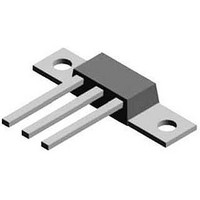
82CNQ030A
Description
DIODE SCHOTTKY 30V 40A D61-8
Manufacturer
Vishay
Datasheet
1.82CNQ030APBF.pdf
(6 pages)
Specifications of 82CNQ030A
Voltage - Forward (vf) (max) @ If
550mV @ 80A
Current - Reverse Leakage @ Vr
5mA @ 30V
Current - Average Rectified (io) (per Diode)
40A
Voltage - Dc Reverse (vr) (max)
30V
Diode Type
Schottky
Speed
Fast Recovery =< 500ns, > 200mA (Io)
Diode Configuration
1 Pair Common Cathode
Mounting Type
Through Hole, Radial
Package / Case
D-61-8
Product
Schottky Rectifiers
Peak Reverse Voltage
30 V
Forward Continuous Current
80 A
Max Surge Current
5100 A
Configuration
Dual Common Cathode
Forward Voltage Drop
0.55 V
Maximum Reverse Leakage Current
5000 uA
Operating Temperature Range
- 55 C to + 150 C
Mounting Style
Through Hole
Lead Free Status / RoHS Status
Contains lead / RoHS non-compliant
Reverse Recovery Time (trr)
-
Lead Free Status / RoHS Status
Contains lead / RoHS non-compliant, Lead free / RoHS Compliant
Other names
82CNQ030
82CNQ030
VS-82CNQ030A
VS-82CNQ030A
VS82CNQ030A
VS82CNQ030A
82CNQ030
VS-82CNQ030A
VS-82CNQ030A
VS82CNQ030A
VS82CNQ030A
Available stocks
Company
Part Number
Manufacturer
Quantity
Price

Part Number:
82CNQ030A
Manufacturer:
IR
Quantity:
20 000
Part Number:
82CNQ030APBF
Manufacturer:
IR
Quantity:
20 000
Company:
Part Number:
82CNQ030ASM
Manufacturer:
IR
Quantity:
584
Part Number:
82CNQ030ASM
Manufacturer:
IR
Quantity:
20 000
Company:
Part Number:
82CNQ030ASMPBF
Manufacturer:
NUVOTON
Quantity:
2 100


VS-82CNQ030A, VS-82CNQ030ASM, VS-82CNQ030ASL
Vishay Semiconductors
Note
(1)
www.vishay.com
2
ABSOLUTE MAXIMUM RATINGS
PARAMETER
Maximum average forward current
See fig. 5
Maximum peak one cycle
non-repetitive surge current per leg
See fig. 7
Non-repetitive avalanche energy per leg
Repetitive avalanche current per leg
ELECTRICAL SPECIFICATIONS
PARAMETER
Maximum forward voltage drop per leg
See fig. 1
Maximum reverse leakage current per leg
See fig. 2
Maximum junction capacitance per leg
Typical series inductance per leg
Maximum voltage rate of change
THERMAL - MECHANICAL SPECIFICATIONS
PARAMETER
Maximum junction and storage
temperature range
Maximum thermal resistance,
junction to case per leg
Maximum thermal resistance,
junction to case per package
Typical thermal resistance,
case to heatsink (D-61-8 only)
Approximate weight
Mounting torque
(D-61-8 only)
Marking device
Pulse width < 300 μs, duty cycle < 2 %
Not for New Design - End of Life - Last Available Purchase Date is 31-August-2011
DiodesAmericas@vishay.com, DiodesAsia@vishay.com,
For technical questions within your region, please contact one of the following:
maximum
minimum
New Generation 3 D-61 Package, 2 x 40 A
SYMBOL
SYMBOL
SYMBOL
T
V
I
dV/dt
R
R
J
I
RM
I
F(AV)
E
FM
FSM
, T
I
C
L
thJC
thCS
AR
AS
S
T
(1)
Stg
(1)
DC operation
See fig. 4
DC operation
Mounting surface, smooth and greased
Device flatness < 5 mils
Case style D-61-8
Case style D-61-8-SM
Case style D-61-8-SL
50 % duty cycle at T
5 μs sine or 3 μs rect. pulse
10 ms sine or 6 ms rect. pulse
T
Current decaying linearly to zero in 1 μs
Frequency limited by T
40 A
80 A
40 A
80 A
T
T
V
Measured lead to lead 5 mm from package body
Rated V
J
J
R
J
= 25 °C
= 125 °C
= 25 °C, I
= 5 V
Schottky Rectifier
R
DC
(test signal range 100 kHz to 1 MHz), 25 °C
AS
= 8 A, L = 1.12 mH
TEST CONDITIONS
TEST CONDITIONS
TEST CONDITIONS
C
= 119 °C, rectangular waveform
J
maximum V
DiodesEurope@vishay.com
T
T
V
J
J
R
= 25 °C
= 125 °C
= Rated V
Following any rated
load condition and with
rated V
A
= 1.5 x V
RRM
R
applied
R
typical
Document Number: 93402
- 55 to 150
VALUES
VALUES
VALUES
10 000
40 (35)
58 (50)
5100
3700
0.85
0.42
0.30
0.28
0.47
0.55
0.37
0.47
280
880
5.5
7.8
82CNQ030ASM
80
82CNQ030ASL
36
Revision: 03-Mar-11
8
5
82CNQ030A
kgf · cm
(lbf · in)
UNITS
UNITS
UNITS
°C/W
V/μs
mA
mJ
nH
oz.
pF
°C
A
A
V
g
Related parts for 82CNQ030A
Image
Part Number
Description
Manufacturer
Datasheet
Request
R

Part Number:
Description:
357-036-542-201 CARDEDGE 36POS DL .156 BLK LOPRO
Manufacturer:
Vishay
Datasheet:
Part Number:
Description:
357-036-542-201 CARDEDGE 36POS DL .156 BLK LOPRO
Manufacturer:
Vishay
Datasheet:
Part Number:
Description:
357-036-542-201 CARDEDGE 36POS DL .156 BLK LOPRO
Manufacturer:
Vishay
Datasheet:
Part Number:
Description:
357-036-542-201 CARDEDGE 36POS DL .156 BLK LOPRO
Manufacturer:
Vishay
Datasheet:
Part Number:
Description:
357-036-542-201 CARDEDGE 36POS DL .156 BLK LOPRO
Manufacturer:
Vishay
Datasheet:
Part Number:
Description:
357-036-542-201 CARDEDGE 36POS DL .156 BLK LOPRO
Manufacturer:
Vishay
Datasheet:
Part Number:
Description:
357-036-542-201 CARDEDGE 36POS DL .156 BLK LOPRO
Manufacturer:
Vishay
Datasheet:
Part Number:
Description:
357-036-542-201 CARDEDGE 36POS DL .156 BLK LOPRO
Manufacturer:
Vishay
Datasheet:
Part Number:
Description:
357-036-542-201 CARDEDGE 36POS DL .156 BLK LOPRO
Manufacturer:
Vishay
Datasheet:
Part Number:
Description:
357-036-542-201 CARDEDGE 36POS DL .156 BLK LOPRO
Manufacturer:
Vishay
Datasheet:
Part Number:
Description:
357-036-542-201 CARDEDGE 36POS DL .156 BLK LOPRO
Manufacturer:
Vishay
Datasheet:
Part Number:
Description:
357-036-542-201 CARDEDGE 36POS DL .156 BLK LOPRO
Manufacturer:
Vishay
Datasheet:
Part Number:
Description:
357-036-542-201 CARDEDGE 36POS DL .156 BLK LOPRO
Manufacturer:
Vishay
Datasheet:
Part Number:
Description:
357-036-542-201 CARDEDGE 36POS DL .156 BLK LOPRO
Manufacturer:
Vishay
Datasheet:
Part Number:
Description:
357-036-542-201 CARDEDGE 36POS DL .156 BLK LOPRO
Manufacturer:
Vishay
Datasheet: