32CTQ030-1PBF Vishay, 32CTQ030-1PBF Datasheet - Page 4
32CTQ030-1PBF
Manufacturer Part Number
32CTQ030-1PBF
Description
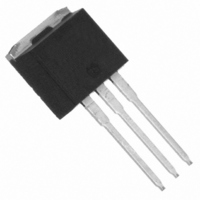
DIODE SCHOTTKY 30V 15A TO262
Manufacturer
Vishay
Datasheets
1.32CTQ030STRL.pdf
(6 pages)
2.VS-32CTQ030SPBF.pdf
(6 pages)
3.32CTQ030-1PBF.pdf
(8 pages)
Specifications of 32CTQ030-1PBF
Diode Configuration
1 Pair Common Cathode
Diode Type
Schottky
Voltage - Forward (vf) (max) @ If
580mV @ 30A
Current - Reverse Leakage @ Vr
1.75mA @ 30V
Current - Average Rectified (io) (per Diode)
15A
Voltage - Dc Reverse (vr) (max)
30V
Speed
Fast Recovery =< 500ns, > 200mA (Io)
Mounting Type
Through Hole, Radial
Package / Case
I²Pak, TO-262 (3 straight leads + tab)
Product
Schottky Rectifiers
Peak Reverse Voltage
30 V
Forward Continuous Current
30 A
Max Surge Current
900 A
Configuration
Dual Common Cathode
Forward Voltage Drop
0.58 V
Maximum Reverse Leakage Current
1750 uA
Operating Temperature Range
- 55 C to + 150 C
Mounting Style
Through Hole
Repetitive Reverse Voltage Vrrm Max
30V
Forward Current If(av)
30A
Forward Voltage Vf Max
580mV
Lead Free Status / RoHS Status
Lead free / RoHS Compliant
Reverse Recovery Time (trr)
-
Lead Free Status / RoHS Status
Lead free / RoHS Compliant, Lead free / RoHS Compliant
Other names
*32CTQ030-1PBF


40CTQ045, 40CTQ045S, 40CTQ045-1
Bulletin PD-20544 rev. D 07/06
4
(2) Formula used: T
Pd = Forward Power Loss = I
Pd
150
145
140
135
130
125
120
115
110
105
100
REV
Fig. 5 - Max. Allowable Case Temperature
= Inverse Power Loss = V
0
Vs. Average Forward Current (Per Leg)
S quare wave (D = 0.50)
80% R ated V applied
see note (2)
Average Forward Current - I
CURRENT
MONIT OR
5
C
= T
DUT
J
10
- (Pd + Pd
R
F(AV)
15
REV
R1
10000
Fig. 7 - Max. Non-Repetitive Surge Current (Per Leg)
x V
1000
x I
100
) x R
DC
FM
R
20
(1 - D); I
S quare Wave Pulse Duration - t
@ (I
10
Fig. 8 - Unclamped Inductive Test Circuit
thJC
F(AV)
R g = 25 ohm
F(AV)
;
25
R
At Any R ated Load Condition
And With Rated V
Following S urge
@ V
/
(A)
IR F P460
D) (see Fig. 6);
L
R1
30
100
= 10 V
RRM
1000
Applied
FREE-WHEEL
40HF L40S 02
p
DIODE
(microsec)
HIGH-S PEED
S WIT CH
18
16
14
12
10
10000
Fig. 6 - Forward Power Loss Characteristics
8
6
4
2
0
0
Average Forward Current - I
D = 0.20
D = 0.25
D = 0.33
D = 0.50
D = 0.75
R MS Limit
5
+
10
(Per Leg)
Vd = 25 Volt
15
www.irf.com
20
DC
F(AV)
25
(A)
30
Related parts for 32CTQ030-1PBF
Image
Part Number
Description
Manufacturer
Datasheet
Request
R

Part Number:
Description:
DIODE SCHOTTKY 30V 15A TO-220AB
Manufacturer:
Vishay
Datasheet:

Part Number:
Description:
DIODE SCHOTTKY 30V 15A TO-262
Manufacturer:
Vishay
Datasheet:

Part Number:
Description:
Schottky Rectifier, 2 x 15 A
Manufacturer:
VISHAY [Vishay Siliconix]
Datasheet:

Part Number:
Description:
SCHOTTKY D2PAK
Manufacturer:
Vishay
Datasheet:

Part Number:
Description:
357-036-542-201 CARDEDGE 36POS DL .156 BLK LOPRO
Manufacturer:
Vishay
Datasheet:
Part Number:
Description:
357-036-542-201 CARDEDGE 36POS DL .156 BLK LOPRO
Manufacturer:
Vishay
Datasheet:
Part Number:
Description:
357-036-542-201 CARDEDGE 36POS DL .156 BLK LOPRO
Manufacturer:
Vishay
Datasheet:
Part Number:
Description:
357-036-542-201 CARDEDGE 36POS DL .156 BLK LOPRO
Manufacturer:
Vishay
Datasheet:
Part Number:
Description:
357-036-542-201 CARDEDGE 36POS DL .156 BLK LOPRO
Manufacturer:
Vishay
Datasheet:
Part Number:
Description:
357-036-542-201 CARDEDGE 36POS DL .156 BLK LOPRO
Manufacturer:
Vishay
Datasheet:
Part Number:
Description:
357-036-542-201 CARDEDGE 36POS DL .156 BLK LOPRO
Manufacturer:
Vishay
Datasheet:
Part Number:
Description:
357-036-542-201 CARDEDGE 36POS DL .156 BLK LOPRO
Manufacturer:
Vishay
Datasheet:
Part Number:
Description:
357-036-542-201 CARDEDGE 36POS DL .156 BLK LOPRO
Manufacturer:
Vishay
Datasheet:
Part Number:
Description:
357-036-542-201 CARDEDGE 36POS DL .156 BLK LOPRO
Manufacturer:
Vishay
Datasheet:
Part Number:
Description:
357-036-542-201 CARDEDGE 36POS DL .156 BLK LOPRO
Manufacturer:
Vishay
Datasheet: