30CPU04PBF Vishay, 30CPU04PBF Datasheet
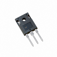
DIODE ULT FAST 400V 15A TO247AC

30CPU04PBF

Manufacturer Part Number
30CPU04PBF
Description
DIODE ULT FAST 400V 15A TO247AC
Manufacturer
Vishay
Series
FRED Pt™r
Datasheets

Specifications of 30CPU04PBF

Voltage - Forward (vf) (max) @ If
1.25V @ 15A
Current - Reverse Leakage @ Vr
10µA @ 400V
Current - Average Rectified (io) (per Diode)
15A
Voltage - Dc Reverse (vr) (max)
400V
Reverse Recovery Time (trr)
60ns
Diode Type
Standard
Speed
Fast Recovery =< 500ns, > 200mA (Io)
Diode Configuration
1 Pair Common Cathode
Mounting Type
Through Hole, Radial
Package / Case
TO-247-3 (Straight Leads), TO-247AC
Product
Ultra Fast Recovery Rectifier
Configuration
Dual Common Cathode
Reverse Voltage
400 V
Forward Voltage Drop
1.25 V
Recovery Time
60 ns
Forward Continuous Current
30 A
Max Surge Current
200 A
Reverse Current Ir
10 uA
Mounting Style
Through Hole
Maximum Operating Temperature
+ 175 C
Minimum Operating Temperature
- 65 C
Lead Free Status / RoHS Status
Lead free / RoHS Compliant
Lead Free Status / RoHS Status
Lead free / RoHS Compliant, Lead free / RoHS Compliant
Other names
*30CPU04PBF
VS-30CPU04PBF
VS-30CPU04PBF
VS30CPU04PBF
VS30CPU04PBF

Available stocks

Company
Part Number
Manufacturer
Quantity
Price
Part Number:
30CPU04PBF
Manufacturer:
VISHAY
Quantity:
500
Part Number:
30CPU04PBF
Manufacturer:
IR
Quantity:
1 000
Part Number:
30CPU04PBF
Manufacturer:
IR
Quantity:
20 000
Company:
Part Number:
30CPU04PBF
Quantity:
70 000
Document Number: 94013
ULTRAFAST RECTIFIER
Absolute Maximum Ratings
• Ultrafast Recovery Time
• Low Forward Voltage Drop
• Low Leakage Current
• 175°C Operating Junction Temperature
• Lead-Free
Description/ Applications
International Rectifier's FRED.. series are the state of the art Ultra fast recovery rectifiers specifically designed with
optimized performance of forward voltage drop and ultra fast recovery time.
The planar structure and the platinum doped life time control, guarantee the best overall performance, ruggedness
and reliability characteristics.
These devices are intended for use in the output rectification stage of SMPS, UPS, DC-DC converters as well as
free-wheeling diode in low voltage inverters and chopper motor drives.
Their extremely optimized stored charge and low recovery current minimize the switching losses and reduce over
dissipation in the switching element and snubbers.
Features
V
I
I
I
T
F(AV)
FSM
FRM
J
RRM
, T
STG
Parameters
Peak Repetitive Peak Reverse Voltage
Average Rectified Forward Current
Total Device (Rated V
Non Repetitive Peak Surge Current, @ 25°C
Peak Repetitive Forward Current
(Rated V
Operating Junction and Storage Temperatures
R
, Square wave, 20 KHz), T
R
), T
C
= 149°C
C
30CPU04PbF
= 149°C
Case Styles
TO247AC
Per Leg
Total Device
Per Leg
Per Leg
- 65 to 175
Max
400
200
15
30
30
30CPU04PbF
Bulletin PD-20674 04/04
Anode
1
I
F(AV)
1
V
Common
Cathode
Common
Cathode
t
rr
Base
R
www.vishay.com
= 60ns
2
= 400V
= 30Amp
2
Units
°C
Anode
V
A
3
2
1

Related parts for 30CPU04PBF

30CPU04PBF Summary of contents

Page 1

... Square wave, 20 KHz Operating Junction and Storage Temperatures J STG Document Number: 94013 Per Leg = 149°C Total Device C Per Leg Per Leg = 149°C C Case Styles 30CPU04PbF TO247AC Bulletin PD-20674 04/04 30CPU04PbF t = 60ns 30Amp F(AV 400V R Max Units 400 200 175 ° ...

Page 2

... Bulletin PD-20674 04/04 Electrical Characteristics @ T Parameters Breakdown Voltage Blocking Voltage V Forward Voltage F I Reverse Leakage Current R C Junction Capacitance T L Series Inductance S Dynamic Recovery Characteristics @ T Parameters t Reverse Recovery Time rr I Peak Recovery Current RRM Q Reverse Recovery Charge rr Thermal - Mechanical Characteristics ...

Page 3

... FM Single Pulse Notes: 1. Duty factor Peak Tj = Pdm x ZthJC+ Tc 0.001 0.01 0.1 1 Characteristics thJC 30CPU04PbF Bulletin PD-20674 04/ 175˚ 150˚ 125˚ 100˚ 25˚C 0 100 200 300 400 Reverse Voltage - V (V) R Vs. Reverse Voltage T = 25˚C ...

Page 4

... Bulletin PD-20674 04/04 180 170 DC 160 150 Square wave (D = 0.50) Rated Vr applied 140 see note (3) 130 Average Forward Current - I Fig Max. Allowable Case Temperature Vs. Average Forward Current 100 200V 125˚ 25˚C 10 100 di /dt (A/µ Fig Typical Reverse Recovery vs. di ...

Page 5

... Reverse Recovery Circuit V = 200V R 0.01 Ω 70µH D.U. /dt dif/dt F IRFP250 0.5 RRM di(rec)M/dt 0.75 I RRM di / Area under curve defined and I RRM (rec Peak rate of change of to point where current during t b portion and 0.50 I RRM RRM 30CPU04PbF Bulletin PD-20674 04/ RRM RRM 2 www.vishay.com 5 ...

Page 6

... Bulletin PD-20674 04/04 Outline Table 3.65 (0.144) 15.90 (0.626) 3.55 (0.139) 15.30 (0.602) 5.70 (0.225) 5.30 (0.208) 20.30 (0.800) 19.70 (0.775 14.80 (0.583) 4.30 (0.170) 14.20 (0.559) 3.70 (0.145) 2.20 (0.087) 1.40 (0.056) MAX. 1.00 (0.039) 3.20 (0.126) MAX. 5.47 (0.216) 5 ...

Page 7

... TO-247AC - Ultrafast Recovery - Voltage Rating (04 = 400V) - Lead-Free Data and specifications subject to change without notice. This product has been designed and qualified for Industrial Level. Qualification Standards can be found on IR's Web site. 30CPU04PbF Bulletin PD-20674 04/04 TAC Fax: (310) 252-7309 04/04 www.vishay.com 7 ...

Page 8

... Except as provided in Vishay's terms and conditions of sale for such products, Vishay assumes no liability whatsoever, and disclaims any express or implied warranty, relating to sale and/or use of Vishay products including liability or warranties relating to fitness for a particular purpose, merchantability, or infringement of any patent, copyright, or other intellectual property right. ...

Related keywords