X-10GQ22-B Omron, X-10GQ22-B Datasheet - Page 6
X-10GQ22-B
Manufacturer Part Number
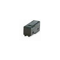
X-10GQ22-B
Description
BASIC SWITCH
Manufacturer
Omron
Series
Xr
Specifications of X-10GQ22-B
Circuit
SPDT
Switch Function
On-Mom
Contact Rating @ Voltage
10A @ 30VDC
Actuator Type
Roller Plunger
Mounting Type
Panel Mount
Termination Style
Screw Terminal
Operating Force
510gf
Contact Form
SPDT
Contact Rating
10 Amps at 125 Volts
Actuator
Roller Plunger
Pole Throw Configuration
SPDT
Switch Function Configuration
N.O./N.C.
Actuator Style
Roller Plunger
Current Rating (max)
10A
Dc Voltage Rating (max)
250VVDC
Contact Material
Silver
Mechanical Life
1000000
Terminal Type
Screw
Product Depth (mm)
17.45mm
Product Length (mm)
49.2mm
Operating Temp Range
-25C to 80C
Mounting Style
Panel Mount/Screw Mount
Lead Free Status / RoHS Status
Lead free / RoHS Compliant
Lead Free Status / RoHS Status
Lead free / RoHS Compliant
Other names
X10GQ22B
X10GQ22BNC
X10GQ22BNC


Safety Precautions
Refer to Safety Precautions for All Basic Switches.
Terminal Connection
When soldering lead wires to the Switch, make sure that the capacity
of the soldering iron is 60 W maximum. Do not take more than 5 s to
solder any part of the Switch. The characteristics of the Switch will
deteriorate if a soldering iron with a capacity of more than 60 W is
applied to any part of the Switch for 5 s or more.
Operation
Mounting Location
• Make sure that the switching frequency or speed is within the
• Make sure that the actuator travel does not exceed the permissible
• Do not use the switch alone in atmospheres such as flammable or
• Switches are generally not constructed with resistance against
• Install the switch in a location that is not directly subject to debris
• Do not use the switch in locations subject to hot water (greater than
specified range.
OT position. The operating stroke must be set to 70% to 100% of
the rated OT.
explosive gases. Arcing and heat generation associated with
switching may cause fires or explosions.
water. Use a protective cover to prevent direct spraying if the switch
is used in locations subject to splashing or spurting oil or water, dust
adhering.
and dust from cutting. The actuator and the switch body must be
protected from accumulated cutting debris and dirt.
60°C) or in water vapor.
1.If the switching speed is extremely slow, the contact may not be
2.If the switching speed is extremely fast, switching shock may
The rated permissible switching speed and frequency indicate the
switching reliability of the Switch.
The life of a Switch is determined at the specified switching speed.
The life varies with the switching speed and frequency even when
they are within the permissible ranges. In order to determine the
life of a Switch model to be applied to a particular use, it is best to
conduct an appropriate durability test on some samples of the
model under actual conditions.
switched smoothly, which may result in a contact failure or
contact welding.
damage the Switch soon. If the switching frequency is too high,
the contact may not catch up with the speed.
Incorrect
Precautions for Correct Use
Terminal box
Precautions for Safe Use
Incorrect
Terminal box
Correct
Correct
Handling
• Do not use the switch outside the specified temperature and
• Mount a cover if the switch is to be installed in a location where
• Subjecting the switch to continuous vibration or shock may result in
• If silver contacts are used with relatively low frequency for a long
• Do not use the switch in atmospheres with high humidity or heat or
• The switch includes contacts. If the switch is used in an atmosphere
• Set the common (COM) terminal to the positive terminal. If it is set
• When using the Switch under an inductive load, the arc
• Since the Switch incorporates a permanent magnet, attention must
• Since a ventilation hole is provided to avoid abnormal corrosion due
atmospheric conditions.
The permissible ambient temperature depends on the model.
(Refer to the specifications in this catalog.) Sudden thermal
changes may cause thermal shock to distort the switch and result
in faults.
worker inattention could result in incorrect operation or accidents.
contact failure or faulty operation due to abrasion powder and in
reduced durability. Excessive vibration or shock will cause the
contacts to operate malfunction or become damaged. Mount the
switch in a location that is not subject to vibration or shock and in a
direction that does not subject the switch to resonance.
time or are used with microloads, the sulfide coating produced on
the contact surface will not be broken down and contact faults will
result. Use a microload switch that uses gold contacts.
in harmful gases, such as sulfide gas (H
(NH
impair functionality, such as with damage due to contacting faults
or corrosion.
with silicon gas, arc energy may cause silicon oxide (SiO
accumulate on the contacts and result in contact failure. If there is
silicon oil, silicon filling, silicon wiring, or other silicon products in the
vicinity of the switch, use a contact protection circuit to limit arcing
and remove the source of the silicon gas.
to the negative terminal, the Switch will not turn OFF.
suppression capability varies depending on current. If the current
becomes 0.6 to 1.2 A or of the time constant L/R exceeds 7 ms, be
sure to provide an arc suppressor.
be paid to the following points:
to operating conditions, provide a dustproofing device in locations
where the Switch is exposed to dust.
(a) Avoid mounting the Switch directly onto a magnetic
(b) Do not subject the Switch to severe shocks.
(c) Avoid placing the Switch in a strong magnetic field.
(d) Be sure to prevent iron dust or iron chips from adhering to the
(e) Do not apply thermal shock to the Switch, or the magnetic flux
Incorrect
3
Incorrect
), nitric acid gas (HNO
substance.
built-in magnet or the magnetic blowout function of the Switch
will be adversely affected.
will be diminished.
3
), or chlorine gas (Cl
(preventing malfunctions)
Correct
Correct
2
S, SO
2
), ammonia gas
2
). Doing so may
Separate the
installation lo-
cation from
heat sources.
2
) to
X
6
Related parts for X-10GQ22-B
Image
Part Number
Description
Manufacturer
Datasheet
Request
R


Part Number:
Description:
BASIC SWITCH
Manufacturer:
Omron
Datasheet:
Part Number:
Description:
Basic / Snap Action / Limit Switches BASIC SWITCH
Manufacturer:
Omron
Datasheet:

Part Number:
Description:
ACCELEROMETER 3X3 DGTL 10-DFN
Manufacturer:
Freescale Semiconductor
Datasheet:

Part Number:
Description:
Board Mount Accelerometers 3-Axis Digital Out Accelerometer
Manufacturer:
Freescale Semiconductor
Datasheet:

Part Number:
Description:
Board Mount Accelerometers LOW G 3-AXIS DGTL ACCEL
Manufacturer:
Freescale Semiconductor
Datasheet:

Part Number:
Description:
Board Mount Accelerometers MEMS Digital Sensor 3-axes Nano
Manufacturer:
STMicroelectronics
Datasheet:

Part Number:
Description:
Board Mount Accelerometers 3.3V Mux Analog Automotive Temp
Manufacturer:
Kionix
Datasheet: