P7MF-06-D Omron, P7MF-06-D Datasheet
P7MF-06-D
Specifications of P7MF-06-D


Related parts for P7MF-06-D


P7MF-06-D Summary of contents
Page 1
... Note: 1. The P7M-06P, P7MF-06, and P7MF-06-D can be used with models for DC loads with an SPST-NO or SPST-NO/SPST-NC contact form or with models for AC loads with an SPST-NO or SPST-NO/SPST-NC contact form. 2. The P7MF-06-D has a built-in diode and can thus be used only with Relays with DC operating coils. Do not use it with a Relay with an AC operating coil. ...
Page 2
Specifications ■ Contact Ratings Models for DC Loads Contact form Model Load Resistive load Item Contact configuration NO NC Contact material Rated load 220 VDC NC Rated carry current NO NC Max. switching voltage NO NC Max. ...
Page 3
... Hz, 1.5-mm double amplitude 2 Destruction: 1,000 m/s when relay is properly mounted into P7M-06P PCB socket 2 500m/s when relay is properly mounted into P7MF-06(-D) socket 2 Malfunction 100 m/s 1,000,000 operations min. (at 18,000 operations/hr VDC −40°C to 60°C (with no icing or condensation) Note: The range is −25°C to 60°C for models with built-in operation indicators. ...
Page 4
Approved Standards UL Recognized CSA Certified Model Coil ratings 12 to 220 VDC MKS1XT@-@ 24 to 240 VAC MKS2XT@-@ MKS1T@-@ MKS2T@-@ IEC Standard/TÜV Certification: IEC61810-1 (Certification No. R50104853) Model Coil ratings 12, 24, 48, 110, 220 VDC MKS1XT@-@ 24, ...
Page 5
Engineering Data Maximum Switching Power MKS1XT@-10 100 DC resistive load inductive load L 0.4 0.1 DC inductive load DC13 class 0. 100 1.000 Switching voltage (V) MKS1T@-10 100 ...
Page 6
Dimensions Models for DC Loads Standard Models MKS1XT-10 MKS2XT-11 Models with Built-in Operation Indicators MKS1XTN-10 MKS2XTN-11 Models for AC Loads Standard Models MKS1T-10 MKS2T-11 Models with Built-in Operation Indicators MKS1TN-10 MKS2TN-11 Models for DC Loads Models with Test Button MKS1XTI-10 ...
Page 7
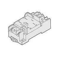
... Terminal Arrangement/Internal Connections (TOP View) P7MF-06 35.5 Note: 1. The internal connections diagram is for the MKS2(X)T@@-11 The P7MF-06-D has polarity. Be careful to wire with the correct polarity. General Purpose Power Relays PCB Mounting Holes (Bottom View 11.05 11.05 Mounting Holes ...
Page 8
... Hold-down Clip PYC-A2 One Set (Two Clips) 5 max. 42.8 4.5 4.5 1.2 Note: The minimum order for the PYC-A2 is ten clips. Socket Mounting Height P7M-06P P7MF-06 P7MF-06-D 8 General Purpose Power Relays 64 MK-S(X) 61 MK-S( MKS ...
Page 9
... Do not install the Relay near IC cards or other items that may be adversely affected by magnetism. Usage Use the Relay mounted in the P7M-06P or P7MF-06(-D) Socket. Test Button • Turn OFF the power supply before operating the test button. Always return the test button to the original position after you use it. ...
Page 10
MEMO 10 General Purpose Power Relays MKS-X ...
Page 11
... Seller within 30 days of receipt of shipment. III. PRECAUTIONS 1. Suitability THE BUYER’S SOLE RESPOINSIBILITY TO ENSURE THAT ANY OMRON PRODUCT IS FIT AND SUFFICIENT FOR USE IN A MOTORIZED VEHICLE APPLICATION. BUYER SHALL BE SOLELY RESPONSIBLE FOR DETERMINING APPROPRIATENESS OF THE PARTICULAR PRODUCT WITH RESPECT TO THE BUYER’ ...
Page 12
... THE OMRON PRODUCT IS PROPERLY RATED AND INSTALLED FOR THE INTENDED USE WITHIN THE OVERALL EQUIPMENT OR SYSTEM. Complete “Terms and Conditions of Sale” for product purchase and use are on Omron’s website at http://www.components.omron.com – under the “About Us” tab, in the Legal Matters section. ...