A7BS-206 Omron, A7BS-206 Datasheet - Page 3
A7BS-206
Manufacturer Part Number
A7BS-206
Description
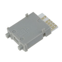
Thumbwheel Switch,BCD,BINARY CODED,Number Of Positions:7,SOLDER Terminal,PUSHBUTTON
Manufacturer
Omron
Series
A7BSr
Specifications of A7BS-206
Output Code
BCD
Read Out
0 ~ 9
Actuator Type
Pushwheel
Mounting Type
Panel Mount, Snap-In (Front)
Termination Style
Card Edge
Component Mounting Area
No
Actuator
Thumbwheel
Lead Free Status / RoHS Status
Lead free / RoHS Compliant
Lead Free Status / RoHS Status
Lead free / RoHS Compliant
Other names
A7BS206


Dimensions
Switches
A7BS-2@@(-1)
Solder Terminals
Thumbwheel Switches with External Stoppers:
A7BS-20@-S(-1)
Refer to page 7 for details.
A7BL-206(-1)
A7BL-207(-1)
Solder Terminals,
Locking Models
• Use A7BS-S Stopper Pins to make dial display restrictions for these Switches.
• Insert the Stopper Pins in the positions required to give the desired display range. For
example, for a display range of 0 to 5, insert a Stopper Pin at position 1 (see following
diagram) to stop the display from going above 5 when the (+) button is pressed, and insert
a Stopper Pin at position 2 to stop the display from going below 0 when the (-) button is
pressed.
22
20.6
24
* If the output code is 06, the dimension is 32.5;
if the output code is 07, the dimension is 43.5.
24
3
3
Ten, 1.2 dia.
8
6.9
± 0.1
7
8
6.9
*
8
6
± 0.1
24.5
0.8
9
5
A
B
3.6
0.8
P=8
B
A
3.8
0
4
P=8
± 0.2
1
3
2
± 0.2
2.8
5.5
* If the output code is 06, the dimension is 32.5;
16
if the output code is 07, the dimension is 43.5.
* If the output code is 06 or 54, the dimension is 32.5;
if the output code is 07 or 55, the dimension is 43.5.
When setting
15.4
2.6
16
24
2
6.1
2.8
2.6
5.5
2.8
Panel Cutout
C +
Pin insertion position (1)
7
0.3
0
8
6
Panel Cutout
Panel thickness: 1 to 3
24.5
9
5
C
Panel thickness: 1 to 3
24.5
+ 0.3
*
0
0
4
Pin insertion position (2)
*
1
3
Solder terminal
2
22.4
Solder terminal
+0.4
0
22.4
20.6
20.6
+ 0.4
0
22
22
Note: 1. The dimensions above include both End
Stopper Pins
Note: 1. Two pins constitute one set.
Note: 1. The dimensions above include both End
Number of
Number of
Switches
Switches
10
(n)
10
(n)
1
2
3
4
5
6
7
8
9
1
2
3
4
5
6
7
8
9
2. Unless otherwise specified, a tolerance of
2. The first shipment is free and is attached
2. Unless otherwise specified, a tolerance of
Caps, and will increase 8 mm for each
Spacer inserted.
±0.4 mm applies to all dimensions.
The tolerance for multiple connection is
±(number of units x 0.4) mm.
to the Switch.
Order the A7BS-S separately if it is
required for maintenance.
Caps, and will increase 8 mm for each
Spacer inserted.
±0.4 mm applies to all dimensions.
The tolerance for multiple connection is
±(number of units x 0.4) mm.
2.4 dia.
(n x 8 + 8)
(n x 8 + 8)
Size A
Size A
16
24
32
40
48
56
64
72
80
88
16
24
32
40
48
56
64
72
80
88
0.4
A7BS/A7BL
(n x 8 + 6)
2.7
(n x 8 + 6)
Size B
Size B
14
22
30
38
46
54
62
70
78
86
14
22
30
38
46
54
62
70
78
86
1.2 dia.
(Unit: mm)
Size C
Size C
14.4
22.4
30.4
38.4
46.8
54.8
62.8
70.8
78.8
86.8
14.4
22.4
30.4
38.4
46.8
54.8
62.8
70.8
78.8
86.8
3
Related parts for A7BS-206
Image
Part Number
Description
Manufacturer
Datasheet
Request
R

Part Number:
Description:
Thumbwheel Switch,BCD,BINARY CODED,Number Of Positions:8,SOLDER Terminal,PUSHBUTTON
Manufacturer:
Omron
Datasheet:

Part Number:
Description:
THUMBWHEEL W/RED CHAR
Manufacturer:
Omron
Datasheet:
Part Number:
Description:
Thumbwheel Switch,BCD,BINARY CODED,Number Of Positions:7,SOLDER Terminal,PUSHBUTTON
Manufacturer:
Omron
Datasheet:
Part Number:
Description:
Thumbwheel Switch,BCD,BINARY CODED,Number Of Positions:8,SOLDER Terminal,PUSHBUTTON
Manufacturer:
Omron
Datasheet:
Part Number:
Description:
Thumbwheel Switch,BCD,BINARY CODED,Number Of Positions:8,SOLDER Terminal,PUSHBUTTON
Manufacturer:
Omron
Datasheet:
Part Number:
Description:
PUSHWHEEL SWITCH +/-
Manufacturer:
Omron
Datasheet:

Part Number:
Description:
PUSHWHEEL SWITCH
Manufacturer:
Omron
Datasheet:
Part Number:
Description:
THUMBWHEEL SWITCH
Manufacturer:
Omron
Datasheet:

Part Number:
Description:
THUMBWHEEL SWITCH
Manufacturer:
Omron
Datasheet:
Part Number:
Description:
THUMBWHEEL
Manufacturer:
Omron
Datasheet:

Part Number:
Description:
Thumbwheel Switch,BCD,BINARY CODED,Number Of Positions:7,SOLDER Terminal,PUSHBUTTON
Manufacturer:
Omron
Datasheet: