G3NA-240B-DC5-24 Omron, G3NA-240B-DC5-24 Datasheet - Page 9
G3NA-240B-DC5-24
Manufacturer Part Number
G3NA-240B-DC5-24
Description
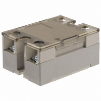
SOLID STATE RELAY
Manufacturer
Omron
Series
G3NAr
Specifications of G3NA-240B-DC5-24
Control Voltage Range
5 VDC to 24 VDC
Load Current
40A
Circuit
SPST-NO (1 Form A)
Output Type
AC, Zero Cross
Voltage - Input
5 ~ 24VDC
Voltage - Load
19 ~ 264 V
Mounting Type
Chassis Mount
Termination Style
Screw Terminal
Package / Case
Hockey Puck
Load Voltage Rating
264 V
Load Current Rating
40 A
Contact Form
1 Form A
Output Device
Triac
Input To Output Isolation Method
Photocoupler
Relay Type
General Purpose Hockey Puck
Operating Voltage Range
19VAC To 264VAC
Isolation Voltage
2500VAC
Control Voltage Type
DC
Relay Terminals
Screw
Load Voltage Max
240VAC
Lead Free Status / RoHS Status
Lead free / RoHS Compliant
On-state Resistance
-
Lead Free Status / Rohs Status
Lead free / RoHS Compliant
Other names
G3NA240BDC524
Z172
Z172
Available stocks
Company
Part Number
Manufacturer
Quantity
Price
Company:

Part Number:
G3NA-240B-DC5-24
Manufacturer:
Omron Electronics Inc-IA Div
Quantity:
135


■ Options (Order Separately)
One-touch Mounting Plate
The One-touch Mounting Plate is used to mount the GN3A to a DIN
Track.
R99-12 FOR G3NA (for the G3NA and G3NE)
Mounting Bracket
Heat Sinks
R99-11 (for the G3NA-240B, G3NA-440B(-2))
Use Mounting Bracket R99-11 so that the G3NA-240B/-440B can be
mounted with the same pitch as that of the G3N-240B.
Y92B-N50 Heat Sink (for the G3NA-205B, G3NA-210B, G3NA-D210B, G3NA-410B, G3NE-210T(L))
For surface mounting, a 30% derating of the load current is required (from the Load Current vs. Ambient Temperature graphs).
The orientation indicated by the external dimensions is not the correct mounting orientation. When opening mounting holes, refer to the
mounting hole dimensions.
21
12.5
Two, M4 mounting
holes for the G3NE
35
30.5±0.3
16
4.6 dia.
8
4
5
100 max.
77 max.
Two, M3 holes
90±0.3
30
44
47.6
Two, M4 mounting
holes for the G3NA
4.6
Two, M4 holes
5.6
44 max.
Two, 3.2-dia. holes
30
5
• When a Relay is mounted to DIN Track, use it within the rating for a
• Use the following DIN Tracks: PFP-100N or PFP-100N2.
To mount the Relay to DIN
Track, first mount it to the
One-touch Mounting Plate
and then attach it to the DIN
Track as shown in the
diagram.
To remove the Relay from
the DIN Track, pull down on
the tab with a screwdriver in
the direction of the arrow.
Relay without a heat sink.
51 max.
6
47 max.
4.5
56
Weight: approx. 200 g
Mounting Holes
35±0.2
Two, 4.4-dia.
or M4 holes
90±0.4
G3NA
9
Related parts for G3NA-240B-DC5-24
Image
Part Number
Description
Manufacturer
Datasheet
Request
R

Part Number:
Description:
RELAY SSR 40A@220VAC ZERO CROSS
Manufacturer:
Omron
Datasheet:

Part Number:
Description:
RELAY SSR 40A 5-24VDC ZERO CROSS
Manufacturer:
Omron
Datasheet:

Part Number:
Description:
SOLID STATE RELAY
Manufacturer:
Omron
Datasheet:

Part Number:
Description:
Solid State Relays 100-120VA/240VAC 40A
Manufacturer:
Omron
Datasheet:

Part Number:
Description:
SSR, PANEL MOUNT, 264VAC, 24VDC, 40A
Manufacturer:
Omron
Datasheet:


Part Number:
Description:
RELAY; SSR; GEN PURP; CUR-RTG 40A; CTRL-V 200-240AC; VOL-RTG 24-240AC; 4 PIN
Manufacturer:
Omron Automation
Datasheet:

Part Number:
Description:
MOUNTING BRACKET FOR G3NA RELAY
Manufacturer:
Omron
Datasheet:

Part Number:
Description:
SOLID STATE RELAY
Manufacturer:
Omron
Datasheet:
Part Number:
Description:
SOLID STATE RELAY
Manufacturer:
Omron
Datasheet:
Part Number:
Description:
RELAY; SSR; GEN PURP; CUR-RTG 10A; CTRL-V 5-24DC; VOL-RTG 24-240AC; 4 PIN
Manufacturer:
Omron Automation
Datasheet:
Part Number:
Description:
RELAY; SSR; ZERO-SWITCHING; CUR-RTG 25A; CTRL-V 5-24DC; VOL-RTG 24-240AC; SCREW
Manufacturer:
Omron Automation
Datasheet:
Part Number:
Description:
RELAY; SSR; GEN PURP; CUR-RTG 20A; CTRL-V 5-24DC; VOL-RTG 24-240AC; 4 PIN
Manufacturer:
Omron Automation
Datasheet: