MBR3035WTPBF Vishay, MBR3035WTPBF Datasheet - Page 4
MBR3035WTPBF
Manufacturer Part Number
MBR3035WTPBF
Description
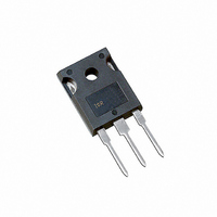
DIODE SCHOTTKY 35V 15A TO247AC
Manufacturer
Vishay
Datasheet
1.MBR3045WTPBF.pdf
(6 pages)
Specifications of MBR3035WTPBF
Diode Configuration
1 Pair Common Cathode
Diode Type
Schottky
Voltage - Forward (vf) (max) @ If
760mV @ 30A
Current - Reverse Leakage @ Vr
1mA @ 35V
Current - Average Rectified (io) (per Diode)
15A
Voltage - Dc Reverse (vr) (max)
35V
Speed
Fast Recovery =< 500ns, > 200mA (Io)
Mounting Type
Through Hole, Radial
Package / Case
TO-247-3 (Straight Leads), TO-247AC
Product
Schottky Diodes
Peak Reverse Voltage
35 V
Forward Continuous Current
30 A
Max Surge Current
1020 A
Configuration
Dual Common Cathode
Forward Voltage Drop
0.76 V
Maximum Reverse Leakage Current
1000 uA
Operating Temperature Range
- 65 C to + 150 C
Mounting Style
Through Hole
Repetitive Reverse Voltage Vrrm Max
35V
Forward Current If(av)
30A
Forward Voltage Vf Max
760mV
Lead Free Status / RoHS Status
Lead free / RoHS Compliant
Reverse Recovery Time (trr)
-
Lead Free Status / RoHS Status
Lead free / RoHS Compliant, Lead free / RoHS Compliant
Other names
*MBR3035WTPBF


MBR3035WTPbF/MBR3045WTPbF
Vishay High Power Products
Note
(1)
www.vishay.com
4
Formula used: T
Pd = Forward power loss = I
Pd
REV
= Inverse power loss = V
Fig. 5 - Maximum Allowable Case Temperature vs.
0
Square wave (D = 0.50)
V
See note (1)
C
I
R
F(AV)
Average Forward Current (Per Leg)
= T
applied
4
J
- Average Forward Current (A)
- (Pd + Pd
8
F(AV)
R1
Current
monitor
REV
x V
12
x I
FM
) x R
R
D.U.T.
(1 - D); I
For technical questions, contact: diodes-tech@vishay.com
at (I
thJC
16
F(AV)
Fig. 7 - Maximum Non-Repetitive Surge Current
10
;
R
Fig. 8 - Unclamped Inductive Test Circuit
DC
/D) (see fig. 6);
t
at V
20
p
Schottky Rectifier, 2 x 15 A
At any rated load condition
and with rated V
following surge
- Square Wave Pulse Duration (µs)
R1
= Rated V
24
R
IRFP460
g
100
= 25 Ω
L
(Per Leg)
RRM
R
applied
1000
Freewheel
40HFL40S02
diode
High-speed
switch
10 000
0
Fig. 6 - Forward Power Loss Characteristics
+
I
D = 0.20
D = 0.25
D = 0.33
D = 0.50
D = 0.75
F(AV)
V
4
d
= 25 V
- Average Forward Current (A)
8
DC
(Per Leg)
12
Document Number: 94293
16
Revision: 14-Aug-08
RMS limit
20
24
Related parts for MBR3035WTPBF
Image
Part Number
Description
Manufacturer
Datasheet
Request
R

Part Number:
Description:
357-036-542-201 CARDEDGE 36POS DL .156 BLK LOPRO
Manufacturer:
Vishay
Datasheet:
Part Number:
Description:
357-036-542-201 CARDEDGE 36POS DL .156 BLK LOPRO
Manufacturer:
Vishay
Datasheet:
Part Number:
Description:
357-036-542-201 CARDEDGE 36POS DL .156 BLK LOPRO
Manufacturer:
Vishay
Datasheet:
Part Number:
Description:
357-036-542-201 CARDEDGE 36POS DL .156 BLK LOPRO
Manufacturer:
Vishay
Datasheet:
Part Number:
Description:
357-036-542-201 CARDEDGE 36POS DL .156 BLK LOPRO
Manufacturer:
Vishay
Datasheet:
Part Number:
Description:
357-036-542-201 CARDEDGE 36POS DL .156 BLK LOPRO
Manufacturer:
Vishay
Datasheet:
Part Number:
Description:
357-036-542-201 CARDEDGE 36POS DL .156 BLK LOPRO
Manufacturer:
Vishay
Datasheet:
Part Number:
Description:
357-036-542-201 CARDEDGE 36POS DL .156 BLK LOPRO
Manufacturer:
Vishay
Datasheet:
Part Number:
Description:
357-036-542-201 CARDEDGE 36POS DL .156 BLK LOPRO
Manufacturer:
Vishay
Datasheet:
Part Number:
Description:
357-036-542-201 CARDEDGE 36POS DL .156 BLK LOPRO
Manufacturer:
Vishay
Datasheet:
Part Number:
Description:
357-036-542-201 CARDEDGE 36POS DL .156 BLK LOPRO
Manufacturer:
Vishay
Datasheet:
Part Number:
Description:
357-036-542-201 CARDEDGE 36POS DL .156 BLK LOPRO
Manufacturer:
Vishay
Datasheet:
Part Number:
Description:
357-036-542-201 CARDEDGE 36POS DL .156 BLK LOPRO
Manufacturer:
Vishay
Datasheet:
Part Number:
Description:
357-036-542-201 CARDEDGE 36POS DL .156 BLK LOPRO
Manufacturer:
Vishay
Datasheet:
Part Number:
Description:
357-036-542-201 CARDEDGE 36POS DL .156 BLK LOPRO
Manufacturer:
Vishay
Datasheet: