MBR4045CT-1PBF Vishay, MBR4045CT-1PBF Datasheet - Page 2
MBR4045CT-1PBF
Manufacturer Part Number
MBR4045CT-1PBF
Description
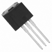
DIODE SCHOTTKY 45V 20A TO262
Manufacturer
Vishay
Datasheets
1.MBR4045CT-1PBF.pdf
(6 pages)
2.MBR4045CT-1PBF.pdf
(6 pages)
3.MBR4045CT-1PBF.pdf
(8 pages)
Specifications of MBR4045CT-1PBF
Diode Configuration
1 Pair Common Cathode
Diode Type
Schottky
Voltage - Forward (vf) (max) @ If
600mV @ 20A
Current - Reverse Leakage @ Vr
1mA @ 45V
Current - Average Rectified (io) (per Diode)
20A
Voltage - Dc Reverse (vr) (max)
45V
Speed
Fast Recovery =< 500ns, > 200mA (Io)
Mounting Type
Through Hole, Radial
Package / Case
I²Pak, TO-262 (3 straight leads + tab)
Product
Schottky Diodes
Peak Reverse Voltage
45 V
Forward Continuous Current
20 A
Max Surge Current
900 A
Configuration
Dual Common Cathode
Forward Voltage Drop
0.6 V
Maximum Reverse Leakage Current
1000 uA
Operating Temperature Range
- 65 C to + 150 C
Mounting Style
Through Hole
Repetitive Reverse Voltage Vrrm Max
45V
Forward Current If(av)
40A
Forward Voltage Vf Max
780mV
Lead Free Status / RoHS Status
Lead free / RoHS Compliant
Reverse Recovery Time (trr)
-
Lead Free Status / RoHS Status
Lead free / RoHS Compliant, Lead free / RoHS Compliant
Other names
*MBR4045CT-1PBF
VS-MBR4045CT-1PBF
VS-MBR4045CT-1PBF
VSMBR4045CT-1PBF
VSMBR4045CT-1PBF
VS-MBR4045CT-1PBF
VS-MBR4045CT-1PBF
VSMBR4045CT-1PBF
VSMBR4045CT-1PBF


Electrical Specifications
2
MBR4045CT, MBRB4045CT, MBR4045CT-1
Voltage Ratings
Thermal-Mechanical Specifications
PreBulletin PD-20051 rev. A 09/01
Absolute Maximum Ratings
I
I
I
E
I
V
I
C
L
dv/dt Max. Voltage Rate of Change
V
V
T
T
R
R
R
wt
T
FRM
FSM
RM
F(AV)
AR
S
R
RWM
AS
FM
T
J
stg
thJC
thCS
thJA
Parameters
Parameters
Max. DC Reverse Voltage (V)
Max. Working Peak Reverse Voltage (V)
Max. Average Forward (Per Leg)
Current
Peak Repetitive Forward
Current
Max.Peak One Cycle Non -Repetitive
Surge Current
Non -Repetitive Avalanche Energy
Repetitive Avalanche Current
Parameters
Max. Forward Voltage Drop
Max. Instantaneus Reverse Current
Max. Junction Capacitance
Typical Series Inductance
(Rated V
Parameters
Max. Junction Temperature Range
Max. Storage Temperature Range
Max. Thermal Resistance
Junction to Case
Typical Thermal Resistance
Case to Heatsink
Max. Thermal Resistance
Junction to Ambient
Approximate Weight
Mounting Torque
R
)
(Per Leg)
(Per Leg)
(Per Leg)
(Per Leg)
(Per Device)
(Per Leg)
(1)
(1)
Min.
Max.
-65 to 150
-65 to 175
Values
Values
Values
2 (0.07)
10,000
12 (10)
0.60
0.78
0.58
0.75
210
0.50
6 (5)
900
900
8.0
1.5
20
40
40
20
50
95
50
1
3
Units Conditions
Units Conditions
Kg-cm
(Ibf-in)
Units Conditions
g (oz.)
V/ µs
°C/W DC operation
°C/W Mounting surface, smooth and greased
°C/W DC operation
mA
mA
mA
nH
pF
°C
°C
V
A
A
A
A
A
V
V
V
Measured from top of terminal to mounting plane
Frequency limited by T
@ 20A
@ 40A
@ 20A
@ 40A
T
T
T
V
@ T
Rated V
T
5µs Sine or 3µs Rect. pulse
10ms Sine or 6ms Rect. pulse
T
Current decaying linearty to zero in 1 µsec
Only for TO-220
For D
Non-lubricated threads
C
J
J
J
J
R
= 25°C, I
= 118° C
= 25 °C
= 100 °C
= 125 °C
= 5V
C
= 118° C, (Rated V
2
Pak and TO-262
R
DC
, square wave, 20kHz
, (test signal range 100Khz to 1Mhz) 25°C
AS
= 3Amps, L = 4.40mH
(1) Pulse Width < 300µs, Duty Cycle <2%
MBR4045CT-1
MBRB4045CT
T
T
Rated DC voltage
MBR4045CT
J
J
= 25 °C
= 125 °C
45
R
J
max. V
)
Following any rated load
condition and with rated
V
RRM
A
= 1.5 x V
applied
www.irf.com
R
typical
Related parts for MBR4045CT-1PBF
Image
Part Number
Description
Manufacturer
Datasheet
Request
R


Part Number:
Description:
DIODE SCHOTTKY 45V 20A TO-262
Manufacturer:
Vishay
Datasheet:

Part Number:
Description:
357-036-542-201 CARDEDGE 36POS DL .156 BLK LOPRO
Manufacturer:
Vishay
Datasheet:
Part Number:
Description:
357-036-542-201 CARDEDGE 36POS DL .156 BLK LOPRO
Manufacturer:
Vishay
Datasheet:
Part Number:
Description:
357-036-542-201 CARDEDGE 36POS DL .156 BLK LOPRO
Manufacturer:
Vishay
Datasheet:
Part Number:
Description:
357-036-542-201 CARDEDGE 36POS DL .156 BLK LOPRO
Manufacturer:
Vishay
Datasheet:
Part Number:
Description:
357-036-542-201 CARDEDGE 36POS DL .156 BLK LOPRO
Manufacturer:
Vishay
Datasheet:
Part Number:
Description:
357-036-542-201 CARDEDGE 36POS DL .156 BLK LOPRO
Manufacturer:
Vishay
Datasheet:
Part Number:
Description:
357-036-542-201 CARDEDGE 36POS DL .156 BLK LOPRO
Manufacturer:
Vishay
Datasheet:
Part Number:
Description:
357-036-542-201 CARDEDGE 36POS DL .156 BLK LOPRO
Manufacturer:
Vishay
Datasheet:
Part Number:
Description:
357-036-542-201 CARDEDGE 36POS DL .156 BLK LOPRO
Manufacturer:
Vishay
Datasheet:
Part Number:
Description:
357-036-542-201 CARDEDGE 36POS DL .156 BLK LOPRO
Manufacturer:
Vishay
Datasheet:
Part Number:
Description:
357-036-542-201 CARDEDGE 36POS DL .156 BLK LOPRO
Manufacturer:
Vishay
Datasheet:
Part Number:
Description:
357-036-542-201 CARDEDGE 36POS DL .156 BLK LOPRO
Manufacturer:
Vishay
Datasheet:
Part Number:
Description:
357-036-542-201 CARDEDGE 36POS DL .156 BLK LOPRO
Manufacturer:
Vishay
Datasheet: