MBR0540PBF Vishay, MBR0540PBF Datasheet - Page 3
MBR0540PBF
Manufacturer Part Number
MBR0540PBF
Description
Schottky (Diodes & Rectifiers) 0.5 Amp 40 Volt
Manufacturer
Vishay
Specifications of MBR0540PBF
Product
Schottky Diodes
Peak Reverse Voltage
40 V
Forward Continuous Current
0.5 A
Max Surge Current
50 A
Configuration
Single
Forward Voltage Drop
0.56 V at 1 A
Maximum Reverse Leakage Current
20 uA
Operating Temperature Range
- 65 C to + 150 C
Mounting Style
SMD/SMT
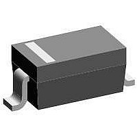
Package / Case
SOD-123
Lead Free Status / RoHS Status
Lead free / RoHS Compliant


Note
(1)
Document Number: 94283
Revision: 14-Aug-08
Formula used: T
Pd = Forward power loss = I
Fig. 1 - Maximum Forward Voltage Drop Characteristics
Fig. 2 - Typical Values of Reverse Current vs.
0
0
0
Fig. 3 - Typical Junction Capacitance vs.
C
= T
5
T
V
J
T
T
FM
0.2
= 125 °C
J
J
J
Reverse Voltage (Per Leg)
= 75 °C
= 25 °C
Reverse Voltage (Per Leg)
T
V
V
- Pd x R
- Forward Voltage Drop (V)
10
10
J
R
R
= 25 °C
- Reverse Voltage (V)
- Reverse Voltage (V)
F(AV)
15
0.4
(Per Leg)
thJC
x V
20
20
;
FM
0.6
For technical questions, contact: diodes-tech@vishay.com
T
at (I
T
25
J
J
T
= 150 °C
= 100 °C
J
F(AV)
= 50 °C
T
T
T
30
30
J
J
J
0.8
= 150 °C
= 125 °C
= 25 °C
/D) (see fig. 4)
Schottky Diode, 0.5 A
35
1.0
40
40
Fig. 4 - Maximum Allowable Case Temperature vs.
Fig. 6 - Maximum Non-Repetitive Surge Current
10
0
0
Fig. 5 - Forward Power Loss Characteristics
Vishay High Power Products
t
Square wave
See note (1)
At any rated load condition
and with rated V
following surge
p
I
I
F(AV)
F(AV)
D = 0.20
D = 0.25
D = 0.33
D = 0.50
D = 0.75
- Square Wave Pulse Duration (µs)
- Average Forward Current (A)
- Average Forward Current (A)
Average Forward Current
0.2
0.2
100
RRM
DC
0.4
applied
0.4
MBR0540PbF
1000
0.6
0.6
D = 0.20
D = 0.25
D = 0.33
D = 0.50
D = 0.75
www.vishay.com
RMS limit
DC
10 000
0.8
0.8
3
Related parts for MBR0540PBF
Image
Part Number
Description
Manufacturer
Datasheet
Request
R

Part Number:
Description:
Manufacturer:
Vishay Semiconductors
Datasheet:

Part Number:
Description:
Schottky (Diodes & Rectifiers) 0.5 Amp 40 Volt
Manufacturer:
Vishay

Part Number:
Description:
357-036-542-201 CARDEDGE 36POS DL .156 BLK LOPRO
Manufacturer:
Vishay
Datasheet:
Part Number:
Description:
357-036-542-201 CARDEDGE 36POS DL .156 BLK LOPRO
Manufacturer:
Vishay
Datasheet:
Part Number:
Description:
357-036-542-201 CARDEDGE 36POS DL .156 BLK LOPRO
Manufacturer:
Vishay
Datasheet:
Part Number:
Description:
357-036-542-201 CARDEDGE 36POS DL .156 BLK LOPRO
Manufacturer:
Vishay
Datasheet:
Part Number:
Description:
357-036-542-201 CARDEDGE 36POS DL .156 BLK LOPRO
Manufacturer:
Vishay
Datasheet:
Part Number:
Description:
357-036-542-201 CARDEDGE 36POS DL .156 BLK LOPRO
Manufacturer:
Vishay
Datasheet:
Part Number:
Description:
357-036-542-201 CARDEDGE 36POS DL .156 BLK LOPRO
Manufacturer:
Vishay
Datasheet:
Part Number:
Description:
357-036-542-201 CARDEDGE 36POS DL .156 BLK LOPRO
Manufacturer:
Vishay
Datasheet:
Part Number:
Description:
357-036-542-201 CARDEDGE 36POS DL .156 BLK LOPRO
Manufacturer:
Vishay
Datasheet:
Part Number:
Description:
357-036-542-201 CARDEDGE 36POS DL .156 BLK LOPRO
Manufacturer:
Vishay
Datasheet:
Part Number:
Description:
357-036-542-201 CARDEDGE 36POS DL .156 BLK LOPRO
Manufacturer:
Vishay
Datasheet:
Part Number:
Description:
357-036-542-201 CARDEDGE 36POS DL .156 BLK LOPRO
Manufacturer:
Vishay
Datasheet:
Part Number:
Description:
357-036-542-201 CARDEDGE 36POS DL .156 BLK LOPRO
Manufacturer:
Vishay
Datasheet: