52CPQ030PBF Vishay, 52CPQ030PBF Datasheet

DIODE SCHOTTKY 30V 25A TO247AC

52CPQ030PBF

Manufacturer Part Number
52CPQ030PBF
Description
DIODE SCHOTTKY 30V 25A TO247AC
Manufacturer
Vishay
Datasheet

Specifications of 52CPQ030PBF

Diode Configuration
1 Pair Common Cathode
Diode Type
Schottky
Voltage - Forward (vf) (max) @ If
480mV @ 25A
Current - Reverse Leakage @ Vr
1.9mA @ 30V
Current - Average Rectified (io) (per Diode)
25A
Voltage - Dc Reverse (vr) (max)
30V
Speed
Fast Recovery =< 500ns, > 200mA (Io)
Mounting Type
Through Hole, Radial
Package / Case
TO-247-3 (Straight Leads), TO-247AC
Product
Schottky Rectifiers
Peak Reverse Voltage
30 V
Forward Continuous Current
50 A
Max Surge Current
2180 A
Configuration
Dual Common Cathode
Forward Voltage Drop
0.55 V
Maximum Reverse Leakage Current
1900 uA
Operating Temperature Range
- 55 C to + 175 C
Mounting Style
Through Hole
Repetitive Reverse Voltage Vrrm Max
30V
Forward Current If(av)
50A
Forward Voltage Vf Max
550mV
Lead Free Status / RoHS Status
Lead free / RoHS Compliant
Reverse Recovery Time (trr)
-
Lead Free Status / RoHS Status
Lead free / RoHS Compliant, Lead free / RoHS Compliant
Other names
*52CPQ030PBF
VS-52CPQ030PBF
VS-52CPQ030PBF
VS52CPQ030PBF
VS52CPQ030PBF

Available stocks

Company
Part Number
Manufacturer
Quantity
Price
Company:
Part Number:
52CPQ030PBF
Quantity:
29 600
* Pb containing terminations are not RoHS compliant, exemptions may apply
Document Number: 94237
Revision: 13-Aug-08
PRODUCT SUMMARY
MAJOR RATINGS AND CHARACTERISTICS
SYMBOL
I
V
I
V
T
VOLTAGE RATINGS
PARAMETER
Maximum DC reverse voltage
Maximum working peak reverse voltage
ABSOLUTE MAXIMUM RATINGS
PARAMETER
Maximum average
forward current
See fig. 5
Maximum peak one cycle
non-repetitive surge current per leg
See fig. 7
Non-repetitive avalanche energy per leg
Repetitive avalanche current per leg
F(AV)
FSM
RRM
F
J
TO-247AC
I
F(AV)
V
R
per device
per leg
Rectangular waveform
t
25 Apk, T
Range
p
Anode
= 5 µs sine
1
For technical questions, contact: diodes-tech@vishay.com
Schottky Rectifier, 2 x 25 A
SYMBOL
1
Common
common
cathode
cathode
2 x 25 A
J
I
I
CHARACTERISTICS
F(AV)
E
Base
FSM
I
= 125 °C (per leg)
30 V
AR
AS
2
2
Anode
50 % duty cycle at T
5 µs sine or 3 µs rect. pulse
10 ms sine or 6 ms rect. pulse
T
Current decaying linearly to zero in 1 µs
Frequency limited by T
2
SYMBOL
3
J
V
= 25 °C, I
V
RWM
R
AS
= 6 A, L = 1.5 mH
FEATURES
• 150 °C T
• Center tap TO-247 package
• Low forward voltage drop
• High frequency operation
• High purity, high temperature epoxy encapsulation for
• Guard ring for enhanced ruggedness and long term
• Lead (Pb)-free (“PbF” suffix)
• Designed and qualified for industrial level
DESCRIPTION
The 52CPQ030PbF center tap Schottky rectifier series has
been optimized for low reverse leakage at high temperature.
The proprietary barrier technology allows for reliable
operation up to 150 °C junction temperature. Typical
applications are in switching power supplies, converters,
freewheeling diodes, and reverse battery protection.
TEST CONDITIONS
C
enhanced mechanical strength and moisture resistance
reliability
= 132 °C, rectangular waveform
J
maximum V
J
operation
52CPQ030PbF
Following any rated load
condition and with rated
V
Vishay High Power Products
A
RRM
- 55 to 150
= 1.5 x V
VALUES
2180
0.38
applied
50
30
30
R
typical
52CPQ030PbF
VALUES
2180
600
25
50
27
6
www.vishay.com
UNITS
UNITS
°C
V
A
V
V
A
RoHS*
COMPLIANT
UNITS
mJ
Available
A
A
Pb-free
1

Related parts for 52CPQ030PBF

52CPQ030PBF Summary of contents

Page 1

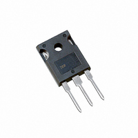
... Common • Designed and qualified for industrial level cathode DESCRIPTION The 52CPQ030PbF center tap Schottky rectifier series has been optimized for low reverse leakage at high temperature. The proprietary barrier technology allows for reliable operation up to 150 °C junction temperature. Typical 30 V applications are in switching power supplies, converters, freewheeling diodes, and reverse battery protection ...

Page 2

... Vishay High Power Products ELECTRICAL SPECIFICATIONS PARAMETER Maximum forward voltage drop per leg See fig. 1 Maximum reverse leakage current per leg See fig. 2 Threshold voltage Forward slope resistance Maximum junction capacitance per leg Typical series inductance per leg Maximum voltage rate of change ...

Page 3

... Reverse Voltage (V) R Fig Typical Junction Capacitance vs. Reverse Voltage (Per Leg 0.20 0.001 0. Rectangular Pulse Duration (s) 1 Characteristics (Per Leg) thJC For technical questions, contact: diodes-tech@vishay.com 52CPQ030PbF Vishay High Power Products T = 150 ° 125 ° 100 ° ° ° ° ...

Page 4

... Vishay High Power Products Square wave (D = 0.50 rated V applied R See note ( Average Forward Current (A) F(AV) Fig Maximum Allowable Case Temperature vs. Average Forward Current (Per Leg) D.U.T. Current monitor Note (1) Formula used ( REV Pd = Forward power loss = F(AV Inverse power loss = REV ...

Page 5

... C = Common cathode - Package TO-247 4 - Schottky “Q” series 5 - Voltage code (030 = 30 V) None = Standard production 6 - PbF = Lead (Pb)-free Tube standard pack quantity: 25 pieces LINKS TO RELATED DOCUMENTS For technical questions, contact: diodes-tech@vishay.com 52CPQ030PbF Vishay High Power Products 6 http://www.vishay.com/doc?95223 http://www.vishay.com/doc?95226 www.vishay.com 5 ...

Page 6

... Vishay product could result in personal injury or death. Customers using or selling Vishay products not expressly indicated for use in such applications their own risk and agree to fully indemnify and hold Vishay and its distributors harmless from and against any and all claims, liabilities, expenses and damages arising or resulting in connection with such use or sale, including attorneys fees, even if such claim alleges that Vishay or its distributor was negligent regarding the design or manufacture of the part ...

Related keywords