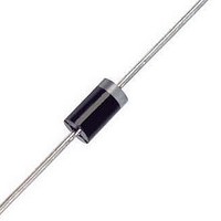
1N5819 ON Semiconductor, 1N5819 Datasheet - Page 5

1N5819
Manufacturer Part Number
1N5819
Description
Schottky (Diodes & Rectifiers) 1A 40V
Manufacturer
ON Semiconductor
Datasheet
1.1N5819.pdf
(7 pages)
Specifications of 1N5819
Product
Schottky Diodes
Peak Reverse Voltage
40 V
Forward Continuous Current
1 A @ Ta=55C
Max Surge Current
25 A
Configuration
Single
Forward Voltage Drop
0.9 V @ 3 A
Maximum Reverse Leakage Current
1000 uA
Operating Temperature Range
- 65 C to + 125 C
Mounting Style
Through Hole
Package / Case
DO-41
Lead Free Status / RoHS Status
Lead free / RoHS Compliant
Available stocks
Company
Part Number
Manufacturer
Quantity
Price
Company:
Part Number:
1N5819
Manufacturer:
TOSHIBA
Quantity:
4 200
Company:
Part Number:
1N5819
Manufacturer:
TOSHIBA
Quantity:
56 000
Part Number:
1N5819
Manufacturer:
MICREL/麦瑞
Quantity:
20 000
Part Number:
1N5819 S4
Manufacturer:
CJ/长电
Quantity:
20 000
Part Number:
1N5819 SS14
Manufacturer:
TOSHIBA/东芝
Quantity:
20 000
Company:
Part Number:
1N5819-1JANTX
Manufacturer:
HITTITE
Quantity:
1 400
Part Number:
1N5819-5255M
Manufacturer:
MICREL/麦瑞
Quantity:
20 000
Part Number:
1N5819-5260M
Manufacturer:
KSY
Quantity:
20 000
sistance for any mounting configuration to be found. For a
given total lead length, lowest values occur when one side of
the rectifier is brought as close as possible to the heatsink.
Terms in the model signify:
T
T
R
R
R
P
A
L
qS
qL
qJ
D
Use of the above model permits junction to lead thermal re-
= Ambient Temperature
= Lead Temperature
= Power Dissipation
0.07
0.05
0.03
0.02
= Thermal Resistance, Junction to Case
= Thermal Resistance, Lead to Heatsink
= Thermal Resistance, Heatsink to Ambient
7.0
5.0
3.0
2.0
1.0
0.7
0.5
0.3
0.2
0.1
20
10
0.1
0.2
v
Figure 7. Typical Forward Voltage
T
F
C
, INSTANTANEOUS FORWARD VOLTAGE (VOLTS)
= 100°C
0.3
0.4
0.5
T
T
C
J
= Junction Temperature
0.6
= Case Temperature
T
0.7
R
A(A)
qS(A)
0.8
T
25°C
NOTE 5. — THERMAL CIRCUIT MODEL
L(A)
(For heat conduction through the leads)
0.9
R
1N5817, 1N5818, 1N5819
qL(A)
1.0 1.1
T
C(A)
http://onsemi.com
R
qJ(A)
T
J
5
0.05
0.03
5.0
3.0
2.0
1.0
0.5
0.3
0.2
0.1
30
20
15
spectively.) Values for thermal resistance components are:
R
R
7.0
5.0
3.0
30
20
10
P
qL
qJ
1.0
0
R
D
(Subscripts A and K refer to anode and cathode sides, re-
Figure 8. Maximum Non−Repetitive Surge Current
qJ(K)
= 100°C/W/in typically and 120°C/W/in maximum
= 36°C/W typically and 46°C/W maximum.
T
Surge Applied at
Rated Load Conditions
J
T
4.0
= 125°C
C(K)
T
f = 60 Hz
2.0
L
R
100°C
75°C
Figure 9. Typical Reverse Current
= 70°C
qL(K)
8.0
25°C
3.0
T
L(K)
V
12
R
, REVERSE VOLTAGE (VOLTS)
R
5.0
qS(K)
T
A(K)
NUMBER OF CYCLES
16
7.0
20
10
24
1 Cycle
20
28
30
32
1N5817
1N5818
1N5819
40
36
70
100
40


