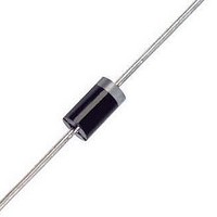
1N5822 ON Semiconductor, 1N5822 Datasheet - Page 5

1N5822
Manufacturer Part Number
1N5822
Description
Schottky (Diodes & Rectifiers) 3A 40V
Manufacturer
ON Semiconductor
Datasheet
1.1N5821.pdf
(8 pages)
Specifications of 1N5822
Product
Schottky Diodes
Peak Reverse Voltage
40 V
Forward Continuous Current
3 A
Max Surge Current
80 A
Configuration
Single
Forward Voltage Drop
0.95 V @ 9.4 A
Maximum Reverse Leakage Current
2000 uA
Operating Temperature Range
- 65 C to + 125 C
Mounting Style
Through Hole
Package / Case
Case 267-05
Lead Free Status / RoHS Status
Lead free / RoHS Compliant
Available stocks
Company
Part Number
Manufacturer
Quantity
Price
Part Number:
1N5822
Manufacturer:
MICREL/麦瑞
Quantity:
20 000
Part Number:
1N5822 SSL34
Manufacturer:
JINGDAO/晶导
Quantity:
20 000
Part Number:
1N5822 X268
Manufacturer:
KEXIN/科信
Quantity:
20 000
Part Number:
1N5822-E
Manufacturer:
LRC/乐山
Quantity:
20 000
Part Number:
1N5822-E3/54
Manufacturer:
VISHAY/威世
Quantity:
20 000
Company:
Part Number:
1N5822-TP
Manufacturer:
MCC
Quantity:
157
Company:
Part Number:
1N5822RL
Manufacturer:
STMicroelectronics
Quantity:
1 900
Company:
Part Number:
1N5822RL
Manufacturer:
ON Semiconductor
Quantity:
2
Company:
Part Number:
1N5822RLG
Manufacturer:
ON
Quantity:
30 000
Company:
Part Number:
1N5822RLG
Manufacturer:
ON
Quantity:
13 500
125
115
105
125
115
105
95
85
75
95
85
75
0.05
0.03
0.02
0.01
1.0
0.5
0.3
0.2
0.1
4.0
2.0
0.2
Figure 1. Maximum Reference Temperature
Figure 3. Maximum Reference Temperature
The temperature of the lead should be measured using a ther‐
mocouple placed on the lead as close as possible to the tie point.
The thermal mass connected to the tie point is normally large
enough so that it will not significantly respond to heat surges
generated in the diode as a result of pulsed operation once
steady-state conditions are achieved. Using the measured
value of T
T
J
5.0
= T
3.0
L
R
+ DT
qJA
R
0.5
qJA
L
, the junction temperature may be determined by:
(°C/W) = 70
7.0
JL
4.0
V
V
(°C/W) = 70
R
R
, REVERSE VOLTAGE (VOLTS)
, REVERSE VOLTAGE (VOLTS)
1.0
5.0
10
50
1N5820
1N5822
50
2.0
40
7.0
40
28
15
28
5.0
10
20
20
20
1N5820, 1N5821, 1N5822
Figure 5. Thermal Response
10
15
15
10
http://onsemi.com
30
15
10
20
8.0
8.0
t, TIME (ms)
20
40
5
50
125
105
115
5.0
40
35
30
25
20
15
10
95
85
75
0
DT
DT
r(t) = normalized value of transient thermal resistance at time, t, i.e.:
r(t
t
1
100
t
1
3.0
p
+ t
JL
JL
0
+ t
p
= P
= the increase in junction temperature above the lead temperature.
, etc.
Figure 2. Maximum Reference Temperature
Figure 4. Steady-State Thermal Resistance
p
) = normalized value of transient thermal resistance at time
pk
200
4.0
1/8
t
• R
1
P
pk
R
qJL
qJA
5.0
2/8
[D + (1 - D) • r(t
V
(°C/W) = 70
R
500
, REVERSE VOLTAGE (VOLTS)
L, LEAD LENGTH (INCHES)
P
pk
TIME
3/8
7.0
1.0 k
1N5821
50
1
DUTY CYCLE = t
PEAK POWER, P
equivalent square power pulse.
4/8
+ t
p
40
2.0 k
10
BOTH LEADS TO HEATSINK,
EQUAL LENGTH
) + r(t
5/8
p
28
) - r(t
MAXIMUM
TYPICAL
LEAD LENGTH = 1/4″
1
5.0 k
20
p
15
)] where:
pk
/t
6/8
1
, is peak of an
15
20
10 k
7/8
10
8.0
20 k
1.0
30


