196 TPI (Test Products Int), 196 Datasheet - Page 16
196
Manufacturer Part Number
196
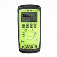
Description
DMM AUTO-RANGE 0-24MA OUTPUT
Manufacturer
TPI (Test Products Int)
Series
190r
Type
Digital (DMM)r
Specifications of 196
Includes
Battery, Test Leads
Style
Handheld
Display Digits
4.75
Display Type
LCD, Bar Graph
Display Count
50000
Function
Voltage, Current, Resistance
Functions, Extra
Continuity, Diode Test
Features
Auto Off, Backlight, Hold, Min/Max, RS-232 Port, Sleep
Ranging
Auto/Manual
Response
Average
Lead Free Status / RoHS Status
Vendor undefined / Vendor undefined
Other names
196TPI
196TPI
290-1425
TPI 196
TPI196
196TPI
290-1425
TPI 196
TPI196
Available stocks
Company
Part Number
Manufacturer
Quantity
Price

Company:
Part Number:
196-015-112-001
Manufacturer:
NorComp Inc.
Quantity:
457
Company:
Part Number:
196-015-112-031
Manufacturer:
NorComp Inc.
Quantity:
457
Company:
Part Number:
196-015-112-551
Manufacturer:
NorComp Inc.
Quantity:
457
Company:
Part Number:
196-015-113L001
Manufacturer:
NorComp Inc.
Quantity:
457


29
k. Record Mode
The record mode saves minimum (MIN) and maximum
(MAX) values measured for a series of readings. The main
part of the LCD displays the actual reading, the MAX value is
constantly displayed on the lower left hand sub-display while
the MIN value is constantly displayed on the lower right
hand sub-display. Activate the function as follows:
1. Depress the
2. The meter will immediately start to record and display
3. Press
4. Press the
MIN/MAX values on the two lower sub-displays.
reading will be displayed.
mode.
REC
REC
button a second time and the AVG(average)
REC
button again to return to normal record
button on the meter.
l. Compare Mode
The compare mode takes the actual reading on the main
display and compares it to LOW and HIGH values,
programmed by the user, on the sub-displays. This is used
to compare components or measurements for acceptable
readings. Activate the function as follows:
1. To use
2. Depress the
3. Depress the
4. Depress the
5. Depress the
6. Repeat steps 4 and 5 until the correct values for all eight
7. After the correct LOW and HIGH values are entered,
8. Measure the circuit or component being compared to the
9. Depress the
range for the function.
HIGH sub-display will start to flash.
number is selected for the position.
above will start to flash.
digits under LOW and HIGH sub-display are entered.
depress the
programmed values. Results will be displayed as PASS
for the acceptable readings, LO for low readings, and HI
for high readings.
the function.
Compare Mode
EDIT
COMP
EDIT
REL
REC
COMP
% or
button. The next digit to the right of 3
button.
button the right hand digit under the
button.
button or turn the rotary switch to exit
HOLD
manually select the correct
buttons until the correct
30