192 TPI (Test Products Int), 192 Datasheet
192
Specifications of 192
192TPI
290-1423
TPI 192
TPI192
Available stocks


192 Summary of contents
Page 1
... CAPACITANCE 100nF 0.1nF (192) 1µF 0.001µF 10µF 0.01µF 100µF 0.1µF Inductance 100mH 0.01mH (Only192) Frequency 50Hz 0.001Hz 500Hz 0.01Hz 5KHz 0.0001KHz 50KHz 0.001KHz 500KHz 0.01KHz Test Voltage Test Current Diode Approx. 3V Approx. 1mA ...
Page 2
TABLE OF CONTENTS A. INTRODUCTION 1. Congratulations ··············· 2. Product Description ············ Declaration of Conformity B. SAFETY CONSIDERATIONS ········· C. TECHNICAL DATA 1. Features and Benefits ··········· 2. Product Applications ··········· 3. Specifications ················ D. MEASUREMENT TECHNIQUES 1. ...
Page 3
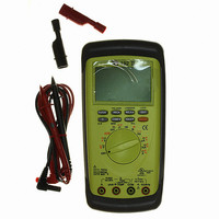
... The meter is a hand-held autoranging DMM. The backlit LCD can display three readings at one time. In addition to basic function of AC/DC V, AC/DC A, Ohm, Diode test, Inductance(Only192), continuity, Capacitance, Frequency, there is the adaptor function. The meter also has RS232 output and software for recording information into a PC. ...
Page 4
B. SAFETY CONSIDERATIONS WARNING! : Please follow manufacturers test procedures whenever possible. Do not attempt to measure unknown voltages or components until a complete understanding of the circuit is obtained. GENERAL GUIDELINES ALWAYS • Test the meter before using to ...
Page 5
C. TECHNICAL DATA 1. Features and benefits Safety Meets CE and IEC 1010 requirements. UL Listed to U.S. and Canadian Safety Standards. True RMS Needed to accurately measure non- sinusoidal AC voltage and current waveforms found on many controls and ...
Page 6
... Specifications IEC 1010 Over Voltage: (190, 192) CAT II-1000VDC, 750VAC CATIII-600V Pollution Degree 2 EC 1010 Over Voltage: (194) CATIII-1000V CATIV-600V Pollution Degree 2 ※ INSTALLATION I·II·III INSTALLATION CATEGORY(OVERVOLTAGE CATEGORY Signal level, special equipment or parts of equipment, telecommunication, electronic etc., with smaller transient overvoltages than INSTALLATION CATEGORY II. ...
Page 7
... F1000V, 11A (Only194) Range 100nF 1uF 10uF Overload 100uF protection 600V Capacitance is max. 5000 counts peak 1000V Inductance (Only 192) peak(Only194) Range 100mH Resolution Accuracy Overload protection Approx. 1mA 600V peak 1000V peak (Only 194) Threshold Overload protection 30digits 600V peak ...
Page 8
... Selects the DC mV function Selects the DCV function Selects the ACV function Selects the DCV function (Push ORANGE button to activate ACV) (Only192) Selects the Diode test function Selects the Ohm function (Push ORANGE button to activate continuity buzzer.) Selects the Capacitance function ...
Page 9
Selects the Inductance function Selects the Frequency function Selects the DC uA function (Push ORANGE button to activate AC uA. Selects the DC mA function (Push ORANGE button to activate AC mA.) Selects the DC A function (Push ORANGE button ...
Page 10
Step by step procedure a. Measuring DC Volts CAUTION Do not attempt to make a voltage measurement if a test lead is plugged in the input jack. Instrument damage and/or personal injury may result. WARNING! Do ...
Page 11
Measuring AC Volts CAUTION Do not attempt to make a voltage measurement if a test lead is plugged in the A or umA input jack. Instrument damage and/or personal injury may result. WARNING! Do not attempt to make a ...
Page 12
Application Notes When measuring the DC current of a flame controller, follow the steps under “Measurement Procedure” above and then proceed with the following: • Set up the meter for making a µA measurement. • Connect the meter to the ...
Page 13
Measuring Resistance WARNING! Do not attempt to make resistance measurements with circuit energized. For best results, remove the resistor completely from the circuit before attempting to measure it. NOTE: To make accurate low ohm measurements, short the ends of ...
Page 14
... COM 3. Plug black test lead into the input jack. 4. Plug the red test lead into the input jack. 5. Set the rotary switch to the function. 6. Connect test leads to capacitor to be measured. 7. Read the capacitor value on the LCD. MAXIMUM READING 20.00mF 120.0uF(Only 192) 26 ...
Page 15
... Disconnect power to circuit to be measured. COM 2. Plug black test lead into the 3. Plug red test lead into the 4. Set the rotary switch to the DMM 192 to the 5. Connect the test leads to the circruit to be measured. 6. Read the Inductance value on the LCD Measuring Frequency ...
Page 16
Record Mode The record mode saves minimum (MIN) and maximum (MAX) values measured for a series of readings. The main part of the LCD displays the actual reading, the MAX value is constantly displayed on the lower left hand ...
Page 17
... Value EDIT unit cr lf Function code Function DCmV DCV ACV Diode Ohm/Continuity Capacitance Frequency Adaptor Inductance 19200 baud none 8 bit 1 bit Function(ASCII code) blank(0x20) -(0x2E)/ (0x20) Measured value(ASCII string) Unit(ASCII string) Carriage Return Line Feed Function code Unit DCV mV DCV V ACV V ...
Page 18
Push button code Push key Code RANGE RANGE AUTO/ RANGE MANUAL REC REC ON/ REC AVG/ REC OFF REL REL ON ref2/ REL OFF COMP COMP ON ref1 ref2/ COMP OFF HOLD HOLD ON/ HOLD OFF ) ref1 is the ...
Page 19
E. ACCESSORIES Standard Accessories 9 Volt Alkaline Battery Fuse 0.5A Fuse 0.44A(Only194) Fuse 10A Fuse 11A(Only194) Test lead Rubber boot Optional Accessories Accessories Demonstration Software Deluxe Test lead set IEC 1010 Deluxe test lead kit Temperature Adaptor Current Adaptor 10/60A ...
Page 20
G. TROUBLE SHOOTING GUIDE Problem Probable Causes Does not power up • Dead or defective battery • Broken wire from battery snap to PCB Won’t display current readings • Open fuse • Open test lead • Improperly connected to circuit ...