ADNB-7051-EV Avago Technologies US Inc., ADNB-7051-EV Datasheet - Page 31
ADNB-7051-EV
Manufacturer Part Number
ADNB-7051-EV
Description
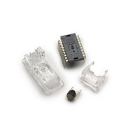
OPT SENSOR BUNDLE SET FOR A7050
Manufacturer
Avago Technologies US Inc.
Specifications of ADNB-7051-EV
Description/function
Laser Mouse Bundle
Interface Type
SPI
Product
Display Modules
Touch Panel
No Touch Panel
For Use With/related Products
ADNS-7050
Lead Free Status / RoHS Status
Lead free / RoHS Compliant
Lead Free Status / RoHS Status
Lead free / RoHS Compliant, Lead free / RoHS Compliant


31
Reserved
LASER_CTRL0
Access: Read/Write
Data Type: Bit field
USAGE: This register is used to control the laser drive. Bits 5 and 7 require complement values in register 0x1F. If the
registers do not contain complementary values for these bits, the laser is turned off and the LP_VALID bit in the MO-
TION register is set to 0. The registers may be written in any order after the power ON reset.
Reserved
Field Name
Range
Match_bit
CAL
Force_Disable
2-0
Bit
Field
Description
Rbin Settings
0 = Laser current range from approximately 2 mA to 7 mA
1 = Laser current range from approximately 5 mA to 13 mA
Match the sensor to the laser characteristics. Set per the bin table specification for the laser in use based on the bin letter.
VCSEL Bin Number
2A
3A
Laser calibration mode
- Write 101b to bits [3,2,1] to set the laser to continuous ON (CW) mode.
- Write 000b to exit laser calibration mode, all other values are not recommended.
Reading the Motion register (0x03 or 0x42) will reset the value to 000b and exit calibration mode.
LASER force disabled
0 = LASER_NEN functions as normal
1 = LASER_NEN output is high.
Address: 0x12-0x1
Address: 0x1a
Reset Value: 0x00
7
Range
Address: 0x1b
6
Reserved
Match_bit
0
0
5
Match_bit
4
Reserved
3
CAL
2
2
CAL
1
1
CAL
0
0
Force_Disable
Related parts for ADNB-7051-EV
Image
Part Number
Description
Manufacturer
Datasheet
Request
R

Part Number:
Description:
OPTICAL MOUSE EVALUATION KIT
Manufacturer:
Avago Technologies US Inc.
Datasheet:

Part Number:
Description:
Display Modules & Development Tools Bundle w/Trim Lens
Manufacturer:
Avago Technologies US Inc.

Part Number:
Description:
Display Modules & Development Tools Bundle w/Trim Lens
Manufacturer:
Avago Technologies US Inc.

Part Number:
Description:
Display Modules & Development Tools Mouse sensor
Manufacturer:
Avago Technologies US Inc.
Part Number:
Description:
Display Modules & Development Tools Mouse sensor
Manufacturer:
Avago Technologies US Inc.

Part Number:
Description:
Display Modules & Development Tools Bundle w/Trim Lens
Manufacturer:
Avago Technologies US Inc.

Part Number:
Description:
Display Modules & Development Tools Sensor+Round Lens
Manufacturer:
Avago Technologies US Inc.
Part Number:
Description:
Display Modules & Development Tools Mouse sensor
Manufacturer:
Avago Technologies US Inc.

Part Number:
Description:
Display Modules & Development Tools Mouse sensor
Manufacturer:
Avago Technologies US Inc.

Part Number:
Description:
Display Modules & Development Tools Bundle w/Trim Lens
Manufacturer:
Avago Technologies US Inc.

Part Number:
Description:
OPTOCOUPLER GATE DRV 2A 16-SOIC
Manufacturer:
Avago Technologies US Inc.
Datasheet:
Part Number:
Description:
OPTOCOUPLER 2CH 2.5A 16-SOIC
Manufacturer:
Avago Technologies US Inc.
Datasheet:

Part Number:
Description:
OPTOCOUPLER GATE DRV 0.4A 16SOIC
Manufacturer:
Avago Technologies US Inc.
Datasheet:

Part Number:
Description:
OPTOCOUPLER 2.0A 250KHZ 8-DIP
Manufacturer:
Avago Technologies US Inc.
Datasheet:

Part Number:
Description:
OPTOCOUPLER 2.0A 250KHZ GW 8-SMD
Manufacturer:
Avago Technologies US Inc.
Datasheet: