ADNS-5000 Avago Technologies US Inc., ADNS-5000 Datasheet - Page 6
ADNS-5000
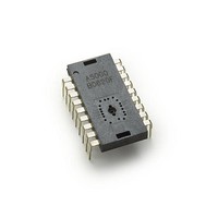
Manufacturer Part Number
ADNS-5000
Description
IC USB OPT MOUSE SENSOR 18-DIP
Manufacturer
Avago Technologies US Inc.
Datasheet
1.ADNS-5000.pdf
(34 pages)
Specifications of ADNS-5000
Product
Optical
Lead Free Status / RoHS Status
Lead free / RoHS Compliant
Lead Free Status / RoHS Status
Lead free / RoHS Compliant, Lead free / RoHS Compliant


PCB Assembly Considerations
1. Insert the sensor and all other electrical components
2. Bend the LED leads 90 degrees and then insert the
3. Insert the LED/clip assembly into PCB.
4. Wave solder the entire assembly in a no-wash solder
5. Place the lens onto the base plate.
6. Remove the protective Kapton tape from optical
7. Insert PCB assembly over the lens onto base plate
8. The optical position reference for the PCB is set by the
9. Install mouse top case.
Figure 7. Typical Application
6
into PCB.
Led into the assembly clip until the snap feature locks
the Led base.
process utilizing solder fixture. The solder fixture
is needed to protect the sensor during the solder
process. The fixture should be designed to expose
the sensor leads to solder while shielding the optical
aperture from direct solder contact.
aperture of the sensor. Care must be taken to keep
contaminants from entering the aperture. Recom-
mend not placing the PCB facing up during the entire
mouse assembly process. Recommend to hold the
PCB first vertically for the Kapton removal process.
aligning post to retain PCB assembly. The sensor ap-
erture ring should self-align to the lens.
base plate and lens. Note that the PCB motion due to
button presses must be minimized to maintain optical
alignment.
Design considerations for improving ESD Performance
The table below shows typical values assuming base
plate construction per the Avago Technologies supplied
IGES file and ADNS-5100 Round lens.
Typical distance
Creepage
Clearance
A5100
40.5mm
32.6mm
A5100-001
17.9mm
9.2mm
Related parts for ADNS-5000
Image
Part Number
Description
Manufacturer
Datasheet
Request
R

Part Number:
Description:
Optical Mouse Sensor,DIP
Manufacturer:
Avago Technologies US Inc.
Datasheet:

Part Number:
Description:
Optical Mouse Sensor,DIP
Manufacturer:
Avago Technologies US Inc.
Datasheet:

Part Number:
Description:
Low Power Wireless LED Sensor
Manufacturer:
Avago Technologies US Inc.
Datasheet:
Part Number:
Description:
USB SoC 3B Optical Sensor
Manufacturer:
Avago Technologies US Inc.
Datasheet:
Part Number:
Description:
Low Power Wireless LED Sensor
Manufacturer:
Avago Technologies US Inc.
Datasheet:
Part Number:
Description:
Optical Mouse Sensor,DIP
Manufacturer:
Avago Technologies US Inc.
Datasheet:

Part Number:
Description:
Trim Lens For ADNS-3530
Manufacturer:
Avago Technologies US Inc.
Datasheet:

Part Number:
Description:
8 DIP SFF Navigation Sensor
Manufacturer:
Avago Technologies US Inc.
Datasheet:

Part Number:
Description:
Trim Lens For ADNS-5090
Manufacturer:
Avago Technologies US Inc.
Datasheet:

Part Number:
Description:
BLACK CLIP FOR ADNS-5000
Manufacturer:
Avago Technologies US Inc.
Datasheet:

Part Number:
Description:
OPTOCOUPLER GATE DRV 2A 16-SOIC
Manufacturer:
Avago Technologies US Inc.
Datasheet:
Part Number:
Description:
OPTOCOUPLER 2CH 2.5A 16-SOIC
Manufacturer:
Avago Technologies US Inc.
Datasheet:

Part Number:
Description:
OPTOCOUPLER GATE DRV 0.4A 16SOIC
Manufacturer:
Avago Technologies US Inc.
Datasheet:

Part Number:
Description:
OPTOCOUPLER 2.0A 250KHZ 8-DIP
Manufacturer:
Avago Technologies US Inc.
Datasheet:

Part Number:
Description:
OPTOCOUPLER 2.0A 250KHZ GW 8-SMD
Manufacturer:
Avago Technologies US Inc.
Datasheet: