MT9T031C12STC Aptina LLC, MT9T031C12STC Datasheet - Page 36
MT9T031C12STC
Manufacturer Part Number
MT9T031C12STC
Description
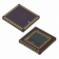
IC SENSOR IMAGE COLOR 48CLCC
Manufacturer
Aptina LLC
Series
Micron®DigitalClarity®r
Type
CMOS Imagingr
Datasheets
1.MT9T031C12STCH_ES.pdf
(12 pages)
2.MT9T031C12STCH_ES.pdf
(2 pages)
3.MT9T031C12STC.pdf
(2 pages)
4.MT9T031C12STC.pdf
(46 pages)
Specifications of MT9T031C12STC
Pixel Size
3.2µm x 3.2µm
Active Pixel Array
2048H x 1536V
Frames Per Second
12 ~ 93
Voltage - Supply
3 V ~ 3.6 V
Package / Case
48-CLCC
Brief Features
Superior Low Light Performance, Programmable Controls, Low Dark Current, High Frame Rate
Supply Voltage Range
3V To 3.6V
Operating Temperature Range
0°C To +60°C
Ic Function
Digital Image Sensor
Lead Free Status / RoHS Status
Lead free / RoHS Compliant
For Use With
557-1450 - KIT HEAD BOARD FOR MT9T031557-1451 - KIT DEV FOR MT9T031
Lead Free Status / Rohs Status
Compliant
Other names
557-1452
Available stocks
Company
Part Number
Manufacturer
Quantity
Price

Part Number:
MT9T031C12STC
Manufacturer:
APTINA
Quantity:
20 000


Black Level
Reset
Standby Control and Chip Enable
Serial Bus Description
Protocol
PDF: 3682685119/Source: 9830567334
MT9T031_DS - Rev.E 5/11 EN
1. Through the two-wire serial interface program R0x07 Bit[1] = 0. This stops the sensor
2. Set STANDBY (pin 7) to HIGH.
Analog offset = Bit[8:0] x 1 LSB
The 1 LSB value in the formula is an estimate amount. It deviates from 1 LSB with
process variation.
R0x49
Digital offset is applied such that the average black level of a frame in a resulting image
equals the value of this register. This adjustment happens after black level calibration.
This register is used to reset the sensor registers to their default, power-up state. To reset
the MT9T031, first write a “1” into bit 0 of this register to put the MT9T031 in reset mode,
then write a “0” into bit 0 to resume operation.
Another way to reset the sensor is through the RESET# (pin 10)
signal to 0V.
The reset operation is an asynchronous reset and the sensor remains in reset as long as
RESET# signal = 0V. In both methods of reset, the sensor register settings returns to their
default states.
There are two steps required to put the sensor in standby mode:
Registers are written to and read from the MT9T031 through the two-wire serial interface
bus. The MT9T031 is a serial interface slave and is controlled by the serial clock (SCLK),
which is driven by the serial interface master. Data is transferred into and out of the
MT9T031 through the serial data (S
chip by a 1.5KΩ resistor. Either the slave or master device can pull the S
the serial interface protocol determines which device is allowed to pull the S
down at any given time.
The two-wire serial defines several different transmission codes, as follows:
• a start bit
• the slave device 8-bit address
• a(n) (no) acknowledge bit
• an 8-bit message
• a stop bit
readout and powers down analog circuitry of the sensor. The sensor stays in standby
mode until the user reprograms R0x07 Bit[1] = 1.
36
DATA
MT9T031: 1/2-Inch 3-Mp Digital Image Sensor
) line. The S
DATA
line is pulled up to 3.3V off-
–
©2006 Aptina Imaging Corporation. All rights reserved.
by pulling the RESET#
Serial Bus Description
DATA
line down—
DATA
line
Related parts for MT9T031C12STC
Image
Part Number
Description
Manufacturer
Datasheet
Request
R

Part Number:
Description:
SENSOR IMAGE VGA COLOR CMOS PLCC
Manufacturer:
Aptina LLC
Datasheet:

Part Number:
Description:
SENSOR IMAGE 1.3MP CMOS 48-CLCC
Manufacturer:
Aptina LLC
Datasheet:

Part Number:
Description:
SENSOR IMAGE 2MP CMOS 48-CLCC
Manufacturer:
Aptina LLC
Datasheet:

Part Number:
Description:
SENSOR IMAGE VGA MONO 52IBGA
Manufacturer:
Aptina LLC
Datasheet:

Part Number:
Description:
SENSOR IMAGE VGA COLOR 48CLCC
Manufacturer:
Aptina LLC
Datasheet:

Part Number:
Description:
SENSOR IMAGE COLOR CMOS 48-PLCC
Manufacturer:
Aptina LLC
Datasheet:

Part Number:
Description:
KIT HEAD BOARD FOR MT9P031
Manufacturer:
Aptina LLC
Datasheet:

Part Number:
Description:
KIT HEAD BOARD FOR MT9D131
Manufacturer:
Aptina LLC
Datasheet:

Part Number:
Description:
KIT HEAD BOARD FOR MT9P031
Manufacturer:
Aptina LLC
Datasheet:

Part Number:
Description:
KIT HEAD BOARD FOR MT9M032
Manufacturer:
Aptina LLC
Datasheet:

Part Number:
Description:
PARALLEL HEADBOARD FOR MT9M032
Manufacturer:
Aptina LLC
Datasheet:
Part Number:
Description:
SENSOR IMAGE VGA COLOR CMOS PLCC
Manufacturer:
Aptina LLC
Datasheet:
Part Number:
Description:
SENSOR IMAGE 2MP CMOS 48-CLCC
Manufacturer:
Aptina LLC
Datasheet:
