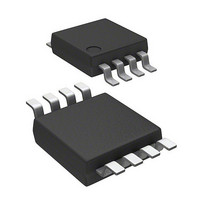
LM3822MM-1.0/NOPB National Semiconductor, LM3822MM-1.0/NOPB Datasheet - Page 10

LM3822MM-1.0/NOPB
Manufacturer Part Number
LM3822MM-1.0/NOPB
Description
IC CURRENT GAUGE PREC 8-MSOP
Manufacturer
National Semiconductor
Type
Battery Chargerr
Datasheet
1.LM3822MM-1.0NOPB.pdf
(13 pages)
Specifications of LM3822MM-1.0/NOPB
Function
Current Gauge
Sensing Method
High-Side
Accuracy
±2%
Voltage - Input
2 ~ 5.5 V
Operating Temperature
-40°C ~ 85°C
Mounting Type
Surface Mount
Package / Case
8-TSSOP, 8-MSOP (0.118", 3.00mm Width)
Operating Supply Voltage (min)
2V
Operating Supply Voltage (max)
5.25V
Operating Temp Range
-40C to 85C
Package Type
MSOP
Mounting
Surface Mount
Pin Count
8
Operating Temperature Classification
Industrial
Lead Free Status / RoHS Status
Lead free / RoHS Compliant
Current - Output
-
Lead Free Status / Rohs Status
Compliant
Other names
LM3822MM-1.0
LM3822MM-1.0TR
LM3822MM-1.0TR
www.national.com
PWM Output and Current
Accuracy
OFFSET
The PWM output is quantized to 1024 levels. Therefore, the
duty cycle can change only in increments of 1/1024.
There is a one-half (0.5) quantization cycle delay in the
output of the PWM circuitry. That is to say that instead of a
duty cycle of N/1024, the duty cycle actually is (N+
The quantization error can be corrected for if a more precise
result is desired. To correct for this error, simply subtract
1/2048 from the measured duty cycle.
The extra half cycle delay will show up as a DC offset of
bit if it is not corrected for. This is approximately 1.0 mA for
1.0 Amp parts, and 10 mA for 2.0 Amp parts.
JITTER
In addition to quantization, the duty cycle will contain some
jitter. The jitter is quite small (for example, the standard
deviation of jitter is only 0.1% for the LM3822-1.0). Statisti-
cally the jitter can cause an error in a current sample. Be-
cause the jitter is a random variable, the mean and standard
deviation are used. The mean, or average value, of the jitter
is zero. The standard deviation (0.1%) can be used to define
the peak error caused from jitter.
The “crest factor” has often been used to define the maxi-
mum error caused by jitter. The crest factor defines a limit
within which 99.7% of the samples fall. The crest factor is
defined as
Since the jitter is a random variable, averaging multiple
outputs will reduce the effective jitter. Obeying statistical
laws, the jitter is reduced by the square root of the number of
readings that are averaged. For example, if four readings of
the duty cycle are averaged, the resulting jitter (and crest
factor) are reduced by a factor of two.
JITTER AND NOISE
Jitter in the PWM output appears as noise in the current
measurement. The Electrical Characteristics show noise
measured in current RMS (root mean square). Arbitrarily one
could specify PWM jitter, as opposed to noise. In either case
the effect results in a random error in an individual current
measurement.
Noise, just like jitter, can be reduced by averaging many
readings. The RMS value of the noise corresponds to one
standard deviation. The “crest factor” can be calculated in
terms of current, and is equal to
noise).
±
0.3% error in the duty cycle.
±
3 sigma (RMS value of the
1
⁄
2
)/1024.
1
⁄
2
10
Noise will also be reduced by averaging multiple readings,
and follows the statistical laws of a random variable.
ACCURACY VERSUS NOISE
The graph shown in Figure 5 illustrates the typical response
of
axis indicates time, and the vertical axis indicates measured
current (the PWM duty cycle has been converted to current).
The graph was generated for an actual current of 500 mA.
The difference between successive readings manifests itself
as jitter in the PWM output or noise in the current measure-
ment (when duty cycle of the PWM output is converted to
current).
The accuracy of the measurement depends on the noise in
the current waveform. The accuracy can be improved by
averaging several outputs. Although there is variation in
successive readings, a very accurate measurement can be
obtained by averaging the readings. For example, on aver-
aging the readings shown in this example, the average
current measurement is 502.3 mA (Figure 5). This value is
very close to the actual value of 500 mA. Moreover, the
accuracy depends on the number of readings that are aver-
aged.
LOW CURRENT MEASUREMENTS
The DC offset of the LM3822-1.0 is typically under 1 mA.
This low offset allows accurate low current measurements.
Even currents in the 10 mA range can be measured with
accuracies typically better than
±
1 Ampere current gauges. In this graph, the horizontal
FIGURE 5. Typical Response of LM3822
±
5%.
10124926


