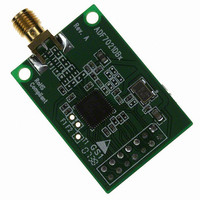
EVAL-ADF7021-NDBZ5 Analog Devices Inc, EVAL-ADF7021-NDBZ5 Datasheet - Page 41

EVAL-ADF7021-NDBZ5
Manufacturer Part Number
EVAL-ADF7021-NDBZ5
Description
Matching Unpopulated
Manufacturer
Analog Devices Inc
Type
Transceiver, FSKr
Datasheet
1.ADF7021-NBCPZ-RL.pdf
(64 pages)
Specifications of EVAL-ADF7021-NDBZ5
Frequency
80MHz ~ 650MHz
Lead Free Status / RoHS Status
Lead free / RoHS Compliant
For Use With/related Products
ADF7021-N
Lead Free Status / Rohs Status
Supplier Unconfirmed
Using the internal RF source, the RF frequencies that can be
used for image calibration are programmable and are odd
multiples of the reference frequency.
Calibration Using External RF Source
IR calibration can also be implemented using an external RF
source. The IR calibration procedure is the same as that used for
the internal RF source, except that an RF tone is applied to the
LNA input.
Calibration Procedure and Setup
The IR calibration algorithm available from Analog Devices, Inc., is
based on a low complexity, 2D optimization algorithm that can
be implemented in an external microprocessor or microcontroller.
To enable the internal RF source, the IR_CAL_SOURCE_
DRIVE_LEVEL bits (R6_DB[28:29]) should be set to the
maximum level. The LNA should be set to its minimum gain
setting, and the AGC should be disabled if the internal source is
being used. Alternatively, an external RF source can be used.
The magnitude of the phase adjust is set by using the IR_PHASE_
ADJUST_MAG bits (R5_DB[20:23]). This correction can be
applied to either the I channel or Q channel, depending on the
value of the IR_PHASE_ADJUST_DIRECTION bit (R5_DB24).
The magnitude of the I/Q gain is adjusted by the IR_GAIN_
ADJUST_MAG bits (R5_DB[25:29]). This correction can be
applied to either the I or Q channel, depending on the value of
RFINB
RFIN
Figure 52. Image Rejection Calibration Using the Internal Calibration Source and a Microcontroller
LNA
INTERNAL
SOURCE
SIGNAL
MUX
PHASE ADJUST
Rev. 0 | Page 41 of 64
PHASE ADJUST
REGISTER 5
GAIN ADJUST
REGISTER 5
FROM LO
I
ADF7021-N
I/Q GAIN/PHASE ADJUST AND
Q
RSSI MEASUREMENT
MICROCONTROLLER
ALGORITHM
IR_GAIN_ADJUST_I/Q bit (R5_DB30), whereas the
IR_GAIN_ADJUST_UP/DN bit (R5_DB31) sets whether
the gain adjustment defines a gain or an attenuation adjust.
The calibration results are valid over changes in the ADF7021-N
supply voltage. However, there is some variation with temperature.
A typical plot of variation in image rejection over temperature
after initial calibrations at −40°C, +25°C, and +85°C is shown in
Figure 53. The internal temperature sensor on the ADF7021-N
can be used to determine if a new IR calibration is required.
INTERFACE
SERIAL
Figure 53. Image Rejection Variation with Temperature After Initial
4
4
POLYPHASE
60
50
40
30
20
10
IF FILTER
0
–60
V
IF BW = 25kHz
WANTED SIGNAL:
RF FREQ = 430MHz
MODULATION = 2FSK
DATA RATE = 9.6kbps,
f
LEVEL= –100dBm
DEV
PRBS9
DD
RSSI READBACK
= 3.0V
= 4kHz
–40
CAL AT +85°C
Calibrations at −40°C, +25°C, and +85°C
7-BIT ADC
–20
LOG AMP
RSSI/
TEMPERATURE (°C)
0
INTERFERER SIGNAL:
RF FREQ = 429.8MHz
MODULATION = 2FSK
DATA RATE = 9.6kbps,
f
DEV
CAL AT +25°C
PRBS11
20
= 4kHz
40
CAL AT –40°C
60
ADF7021-N
80
100


