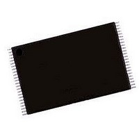
AM29LV160DB-120EI Spansion Inc., AM29LV160DB-120EI Datasheet - Page 13

AM29LV160DB-120EI
Manufacturer Part Number
AM29LV160DB-120EI
Description
Flash Memory IC
Manufacturer
Spansion Inc.
Datasheets
1.AM29LV160DT-70EI.pdf
(49 pages)
2.AM29LV160DT-70EC.pdf
(49 pages)
3.AM29LV160DT-120EC.pdf
(52 pages)
Specifications of AM29LV160DB-120EI
Memory Configuration
2M X 8 / 1M X 16
Ic Interface Type
Parallel
Access Time
120ns
Memory Case Style
TSOP
No. Of Pins
48
Mounting Type
Surface Mount
Supply Voltage
3V
Supply Voltage Max
3.6V
Available stocks
Company
Part Number
Manufacturer
Quantity
Price
Part Number:
AM29LV160DB-120EI
Manufacturer:
AMD
Quantity:
20 000
RESET#: Hardware Reset Pin
The RESET# pin provides a hardware method of re-
setting the device to reading array data. When the
system drives the RESET# pin to V
riod of t
operation in progress, tristates all data output pins,
and ignores all read/write attempts for the duration of
the RESET# pulse. The device also resets the internal
state machine to reading array data. The operation
that was interrupted should be reinitiated once the de-
vice is ready to accept another command sequence,
to ensure data integrity.
Current is reduced for the duration of the RESET#
pulse. When RESET# is held at V
draws CMOS standby current (I
held at V
rent will be greater.
The RESET# pin may be tied to the system reset cir-
cuitry. A system reset would thus also reset the Flash
22358B7 May 5, 2006
RP
IL
, the device immediately terminates any
but not within V
SS
±0.3 V, the standby cur-
SS
CC4
IL
±0.3 V, the device
for at least a pe-
). If RESET# is
D A T A
Am29LV160D
S H E E T
memory, enabling the system to read the boot-up firm-
ware from the Flash memory.
If RESET# is asserted during a program or erase op-
eration, the RY/BY# pin remains a “0” (busy) until the
internal reset operation is complete, which requires a
time of t
system can thus monitor RY/BY# to deter mine
whether the reset operation is complete. If RESET#
is asserted when a program or erase operation is not
executing (RY/BY# pin is “1”), the reset operation is
completed within a time of t
ded Algorithms). The system can read data t
the RESET# pin returns to V
Refer to the AC Characteristics tables for RESET# pa-
rameters and to Figure 14 for the timing diagram.
Output Disable Mode
When the OE# input is at V
disabled. The output pins are placed in the high im-
pedance state.
READY
(during Embedded Algorithms). The
IH
READY
, output from the device is
IH
.
(not during Embed-
RH
after
11


