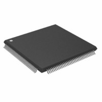
ADSP-2191MBSTZ-140 Analog Devices Inc, ADSP-2191MBSTZ-140 Datasheet - Page 5

ADSP-2191MBSTZ-140
Manufacturer Part Number
ADSP-2191MBSTZ-140
Description
IC,DSP,16-BIT,CMOS,QFP,144PIN,PLASTIC
Manufacturer
Analog Devices Inc
Series
ADSP-21xxr
Type
Fixed Pointr
Specifications of ADSP-2191MBSTZ-140
Interface
Host Interface, SPI, SSP, UART
Clock Rate
140MHz
Non-volatile Memory
External
On-chip Ram
160kB
Voltage - I/o
3.00V, 3.30V
Voltage - Core
2.50V
Operating Temperature
-40°C ~ 85°C
Mounting Type
Surface Mount
Package / Case
144-LQFP
Device Core Size
16b
Clock Freq (max)
140MHz
Mips
140
Device Input Clock Speed
140MHz
Ram Size
160KB
Operating Supply Voltage (typ)
2.5/3.3V
Operating Supply Voltage (min)
2.37/2.97V
Operating Supply Voltage (max)
2.63/3.6V
Operating Temp Range
-40C to 85C
Operating Temperature Classification
Industrial
Mounting
Surface Mount
Pin Count
144
Package Type
LQFP
Lead Free Status / RoHS Status
Lead free / RoHS Compliant
Lead Free Status / RoHS Status
Lead free / RoHS Compliant
Other names
ADSP-2191MBSTZ140
Available stocks
Company
Part Number
Manufacturer
Quantity
Price
Company:
Part Number:
ADSP-2191MBSTZ-140
Manufacturer:
MAXIM
Quantity:
101
Company:
Part Number:
ADSP-2191MBSTZ-140
Manufacturer:
Analog Devices Inc
Quantity:
10 000
Three programmable interval timers generate periodic inter-
rupts. Each timer can be independently set to operate in one of
three modes:
Each timer has one bidirectional pin and four registers that
implement its mode of operation: A 7-bit configuration register,
a 32-bit count register, a 32-bit period register, and a 32-bit
pulsewidth register. A single status register supports all three
timers. A bit in each timer’s configuration register enables or
disables the corresponding timer independently of the others.
Memory Architecture
The ADSP-2191M DSP provides 64K words of on-chip SRAM
memory. This memory is divided into four 16K blocks located
on memory Page 0 in the DSP’s memory map. In addition to the
Figure 2. Memory Map
Internal (On-Chip) Memory
The ADSP-2191M’s unified program and data memory space
consists of 16M locations that are accessible through two 24-bit
address buses, the PMA and DMA buses. The DSP uses slightly
REV. 0
Pulse Waveform Generation mode
Pulsewidth Count/Capture mode
External Event Watchdog mode
EXTERNAL
INTERNAL
INTERNAL
MEMORY
MEMORY
MEMORY
(16- BIT)
PAGES 192–254
PAGES 128–191
PAGES 64–127
PAGES 1–63
64K WORD
MEMORY
PAGES
PAGE 255
PAGE 0
BLOCK3, 16-BIT
BLOCK2, 16-BIT
BOOT ROM, 24-BIT
BLOCK1, 24-BIT
BLOCK0, 24-BIT
BANK3
BANK2
BANK1
BANK0
(MS3)
(MS2)
(MS1)
(MS0)
RESERVED
0 FF 03FF
0 FF 0000
0 FF FFFF
0 FF 0400
0 C0 0000
0 80 0000
0 40 0000
0 01 0000
0 00 C000
0 00 8000
0 00 4000
0 00 0000
ADDRESS
LOGICAL
–5–
internal and external memory space, the ADSP-2191M can
address two additional and separate off-chip memory spaces: I/O
space and boot space.
As shown in
populate all of Page 0. The entire DSP memory map consists of
256 pages (Pages 0 255), and each page is 64K words long.
External memory space consists of four memory banks (banks
0–3) and supports a wide variety of SRAM memory devices. Each
bank is selectable using the memory select pins (MS3–0) and has
configurable page boundaries, waitstates, and waitstate modes.
The 1K word of on-chip boot-ROM populates the top of
Page 255 while the remaining 254 pages are addressable off-chip.
I/O memory pages differ from external memory pages in that I/O
pages are 1K word long, and the external I/O pages have their
own select pin (IOMS). Pages 0–7 of I/O memory space reside
on-chip and contain the configuration registers for the peripher-
als. Both the core and DMA-capable peripherals can access the
DSP’s entire memory map.
BOOT MEMORY
PAGES 1–254
64K WORD
16-BIT
(BMS)
BANKS OF EXTERNAL MEMORY.
LOWER PAGE BOUNDARIES
BOUNDARIES SHOWN ARE
ARE CONFIGURABLE FOR
BANK SIZES AT RESET.
Figure
0 FE FFFF
0 01 0000
ADDRESS
LOGICAL
2, the DSP’s two internal memory blocks
PAGES 8–255
I/O MEMORY
PAGES 0–7
EXTERNAL
INTERNAL
1K WORD
1K WORD
16- BIT
(IOMS)
ADSP-2191M
MEMORY SELECTS (MS)
FOR PORTIONS OF THE
MEMORY MAP APPEAR
WITH THE SELECTED
MEMORY.
8-BIT 10-BIT
ADDRESS
0 FF 3FF
0 08 000
0 07 3FF
0 00 000
LOGICAL


