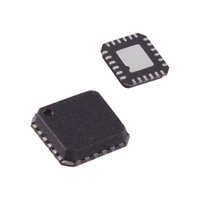
ADN2871ACPZ-RL Analog Devices Inc, ADN2871ACPZ-RL Datasheet - Page 4

ADN2871ACPZ-RL
Manufacturer Part Number
ADN2871ACPZ-RL
Description
IC,Laser Diode/LED Driver,LLCC,24PIN,PLASTIC
Manufacturer
Analog Devices Inc
Type
Laser Diode Driver (Fiber Optic)r
Datasheet
1.ADN2871ACPZ-RL.pdf
(20 pages)
Specifications of ADN2871ACPZ-RL
Data Rate
4.25Gbps
Number Of Channels
1
Voltage - Supply
3 V ~ 3.6 V
Current - Supply
32mA
Current - Modulation
90mA
Current - Bias
100mA
Operating Temperature
-40°C ~ 85°C
Package / Case
24-VFQFN, CSP Exposed Pad
Mounting Type
Surface Mount
Lead Free Status / RoHS Status
Lead free / RoHS Compliant
ADN2871
Parameter
ALARM OUTPUT (FAIL)
IBMON/IMMON DIVISION RATIO
SUPPLY
1
2
3
4
5
6
7
8
9
10
11
12
Temperature range: –40°C to +85°C.
Measured into a single-ended 15 Ω load (22 Ω resistor in parallel with digital scope 50 Ω input) using a 1111111100000000 pattern at 2.5 Gbps, shown in Figure 2.
Guaranteed by design and characterization. Not production tested.
Measured into a single-ended 15 Ω load using a K28.5 pattern at 2.5 Gbps, shown in Figure 2.
Measured into a differential 30 Ω (43 Ω differential resistor in parallel with a digital scope of 50 Ω input) load using a 1111111100000000 pattern at 4.25 Gbps, as
shown in Figure 3.
Measured into a differential 30 Ω load using a K28.5 pattern at 4.25 Gbps, as shown in Figure 3.
Measured into a differential 30 Ω load using a K28.5 pattern at 2.7Gbps, as shown in Figure 3.
When the voltage on DATAP is greater than the voltage on DATAN, the modulation current flows in the IMODP pin.
Guaranteed by design. Not production tested.
IBIAS/IBMON ratio stability is defined in SFF-8472 Revision 9 over temperature and supply variation.
See the I
All V
V
V
IBIAS/IBMON
IBIAS/IBMON
IBIAS/IBMON
IBIAS/IBMON Stability
IMOD/IMMON
IBMON Compliance Voltage
I
V
CC
OFF
ON
CC
11
CC
(with respect to GND)
pins should be shorted together.
CC
minimum for power calculation in the Power Consumption section.
3
3
3
9
3, 10
12
ADN2871
Figure 2. High Speed Electrical Test Single-Ended Output Circuit
ADN2871
Figure 3. High Speed Electrical Test Differential Output Circuit
IMODP
IMODN
IMODP
22Ω
43Ω
R
V
R
CC
Rev. A | Page 4 of 20
80kHz → 27GHz
Min
76
85
92
3.0
0
80kHz → 27GHz
80kHz → 27GHz
V
L
BIAS TEE
L
L
CC
V
V
BIAS TEE
BIAS TEE
CC
CC
C
C
C
Typ
>1.8
<1.3
94
100
100
42
32
3.3
TO HIGH SPEED
DIGITAL
OSCILLOSCOPE
50Ω DIFFERENTIAL INPUT
TO HIGH SPEED
DIGITAL
OSCILLOSCOPE
50Ω INPUT
Max
112
115
108
±5
1.3
3.6
Unit
V
V
A/A
A/A
A/A
%
A/A
V
mA
V
Conditions/Comments
Voltage required at FAIL for
IBIAS and IMOD to turn off
when FAIL asserted
Voltage required at FAIL for
IBIAS and IMOD to stay on
when FAIL asserted
2 mA < IBIAS < 11 mA
11 mA < IBIAS < 50 mA
50 mA < IBIAS < 100 mA
10 mA < IBIAS < 100 mA
When IBIAS = IMOD = 0


