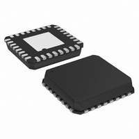
ADN2847ACPZ-32-RL Analog Devices Inc, ADN2847ACPZ-32-RL Datasheet - Page 4

ADN2847ACPZ-32-RL
Manufacturer Part Number
ADN2847ACPZ-32-RL
Description
IC,Laser Diode/LED Driver,LLCC,32PIN,PLASTIC
Manufacturer
Analog Devices Inc
Type
Laser Diode Driver (Fiber Optic)r
Datasheet
1.ADN2847ACPZ-32-RL.pdf
(16 pages)
Specifications of ADN2847ACPZ-32-RL
Data Rate
3.3Gbps
Number Of Channels
1
Voltage - Supply
3 V ~ 3.6 V
Current - Supply
50mA
Current - Modulation
80mA
Current - Bias
100mA
Operating Temperature
-40°C ~ 85°C
Package / Case
32-VFQFN, CSP Exposed Pad
Mounting Type
Surface Mount
Package
32LFCSP EP
Number Of Channels Per Chip
1
Operating Supply Voltage
3 to 3.6 V
Lead Free Status / RoHS Status
Lead free / RoHS Compliant
ADN2847
Parameter
IBMON, IMMON, IMPDMON, IMPDMON2
SUPPLY
1
2
3
4
5
6
7
TIMING DIAGRAMS
The high speed performance for the die version of ADN2847 can be achieved when using the bonding diagram shown in Figure 6.
Measured into a 25 Ω load using a 11110000 pattern at 2.5 Gbps.
When the voltage on DATAP is greater than the voltage on DATAN, the modulation current flows in the IMODP pin.
Guaranteed by design and characterization. Not production tested.
IDTONE can cause eye distortion.
I
All V
CCMIN
Figure 3. Rise Time Distribution Under Worst-Case Operating Conditions
IBMON, IMMON Division Ratio
IMPDMON, IMPDMON2
IMPDMON to IMPDMON2 Matching
Compliance Voltage
I
V
CC
CC
CC
6
for power calculation in the Power Consumption section is the typical I
7
pins should be shorted together.
40
30
20
10
0
76
78
80
82
84
RISE TIME (ps)
86
88
DATAP/DATAN
90
92
CLKP
94
96
98
Min
0
3.0
100
Figure 2. Setup and Hold Time
Rev. A | Page 4 of 16
Typ
100
1
50
3.3
SETUP
CC
t
S
given.
Max
2
V
3.6
CC
Figure 4. Fall Time Distribution Under Worst-Case Operating Conditions
−1.2
40
30
20
10
HOLD
0
80
t
H
Unit
A/A
A/A
%
V
mA
V
82
84
86
Conditions/Comments
I
I
MPD
BIAS
88
= I
= 1200 μA
FALL TIME (ps)
90
MOD
92
= 0
94
96
98
100 102 104


