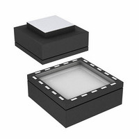
ADIS16251ACCZ Analog Devices Inc, ADIS16251ACCZ Datasheet - Page 20

ADIS16251ACCZ
Manufacturer Part Number
ADIS16251ACCZ
Description
IC,Acceleration Detector,LGA,20PIN,PLASTIC
Manufacturer
Analog Devices Inc
Series
iSensor™r
Datasheet
1.ADIS16251PCBZ.pdf
(24 pages)
Specifications of ADIS16251ACCZ
Range °/s
±20°/s, ±40°/s, ±80°/s
Sensitivity
±0.2%
Typical Bandwidth
49Hz
Voltage - Supply
4.75 V ~ 5.25 V
Current - Supply
18mA
Output Type
SPI
Operating Temperature
-40°C ~ 85°C
Package / Case
20-LGA
Lead Free Status / RoHS Status
Lead free / RoHS Compliant
For Use With
ADIS16251/PCBZ - BOARD EVALUATION FOR ADIS16251
Lead Free Status / RoHS Status
Lead free / RoHS Compliant
Other names
Q3234523
ADIS16251
SECOND-LEVEL ASSEMBLY
The ADIS16251 can be attached to the second-level assembly
board using SN63 (or equivalent) or a Pb-free solder. Figure 20
and Table 40 provide acceptable solder reflow profiles for each
solder type. Please note that these profiles may not be the opti-
mum profile for the user’s application. In no case should 260°C
be exceeded. It is recommended that the user develop a reflow
profile based upon the specific application.
In general, the lowest peak temperature and shortest dwell time
above the melt temperature of the solder result in less shock and
less stress to the product. In addition, evaluating the cooling
rate and peak temperature can result in a more reliable assembly.
Table 40. Acceptable Solder Reflow Profiles
Profile Feature
Average Ramp Rate (T
Preheat
T
Time Maintained Above Liquidous Temperature (T
Peak Temperature (T
Time Within 5°C of Actual T
Ramp-Down Rate
Time 25°C to T
1
Per IPC/JEDEC J-STD-020C.
SMAX
Minimum Temperature (T
Maximum Temperature (T
Time (Between T
Ramp-Up Rate
Liquidous Temperature (T
Time (t
to T
L
L
)
p
SMIN
P
)
L
to T
to T
P
SMAX
p
)
SMAX
SMIN
L
)
) (t
)
)
s
)
1
L
)
Rev. A | Page 20 of 20
T
T
P
L
Sn63/Pb37
3°C/sec max
100°C
150°C
60 sec to 120 sec
3°C/sec
183°C
60 sec to 150 sec
240°C + 0°C/–5°C
10 sec to 30 sec
6°C/sec max
6 min max
T
SMIN
T
SMAX
Figure 20. Acceptable Solder Reflow Profiles
PREHEAT
t
25°C TO PEAK
t
S
RAMP-UP
Conditions
TIME
Pb-Free
3°C/sec max
150°C
200°C
60 sec to 180 sec
3°C/sec
217°C
60 sec to 150 sec
260°C + 0°C/–5°C
20 sec to 40 sec
6°C/sec max
8 min max
RAMP-DOWN
t
P
t
L
CRITICAL ZONE
T
L
TO T
P


