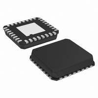
ADCMP566BCP Analog Devices Inc, ADCMP566BCP Datasheet - Page 6

ADCMP566BCP
Manufacturer Part Number
ADCMP566BCP
Description
HIGH SPEED COMPARATOR
Manufacturer
Analog Devices Inc
Type
with Latchr
Datasheet
1.ADCMP566BCPZ.pdf
(16 pages)
Specifications of ADCMP566BCP
Rohs Compliant
NO
Rohs Status
RoHS non-compliant
Number Of Elements
2
Output Type
Complementary, Differential, ECL, Open-Emitter
Voltage - Supply
±4.75 V ~ 5.25 V
Mounting Type
Surface Mount
Package / Case
32-LFCSP
For Use With
EVAL-ADCMP566BCPZ - BOARD EVALUATION ADCMP566BPZ
Lead Free Status / RoHS Status
ADCMP566
PIN CONFIGURATION AND FUNCTION DESCRIPTIONS
Table 3. ADCMP566 Pin Descriptions
Pin No.
1
2
3
4
5
6
7
8
9
10
11
12
13
14
15
16
17
18
19
20
21
GND
−INA
+INA
V
V
+INB
−INB
GND
GND
LEB
LEB
NC
GND
QB
QB
GND
V
NC
V
V
V
Mnemonic
CC
CC
EE
EE
CC
CC
Function
Analog Ground
Inverting analog input of the differential input stage for Channel A. The inverting A input must be driven
in conjunction with the noninverting A input.
Noninverting analog input of the differential input stage for Channel A. The noninverting A input must
be driven in conjunction with the inverting A input.
Positive Supply Terminal
Positive Supply Terminal
Noninverting analog input of the differential input stage for Channel B. The noninverting B input must
be driven in conjunction with the inverting B input.
Inverting analog input of the differential input stage for Channel B. The inverting B input must be driven
in conjunction with the noninverting B input.
Analog Ground
Analog Ground
One of two complementary inputs for Channel B Latch Enable. In the compare mode (logic low), the
output will track changes at the input of the comparator. In the latch mode (logic high), the output will
reflect the input state just prior to the comparator’s being placed in the latch mode. LEB must be driven
in conjunction with LEB .
One of two complementary inputs for Channel B Latch Enable. In the compare mode (logic high), the
output will track changes at the input of the comparator. In the latch mode (logic low), the output will
reflect the input state just prior to the comparator’s being placed in the latch mode. LEB must be driven
in conjunction with LEB.
No Connect. Leave pin unconnected.
Digital Ground
One of two complementary outputs for Channel B. QB will be at logic low if the analog voltage at the
noninverting input is greater than the analog voltage at the inverting input (provided the comparator is
in the compare mode). See the LEB description (Pin 11) for more information.
One of two complementary outputs for Channel B. QB will be at logic high if the analog voltage at the
noninverting input is greater than the analog voltage at the inverting input (provided the comparator is
in the compare mode). See the LEB description (Pin 11) for more information.
Digital Ground
Negative Supply Terminal
No Connect. Leave pin unconnected.
Negative Supply Terminal
Positive Supply Terminal
Positive Supply Terminal
–INA
+INA
+INB
–INB
Figure 2. ADCMP566 Pin Configuration
GND
GND
V
V
CC
CC
1
2
3
4
5
6
7
8
Rev. 0 | Page 6 of 16
NC = NO CONNECT
(Not to Scale)
ADCMP566
PIN 1
INDICATOR
TOP VIEW
03633-0-002
24
23 NC
22 V
21 V
20 V
19 V
18 NC
17 V
V
EE
EE
CC
CC
EE
EE


